What Pulley Lagging Does on a Conveyor Pulley
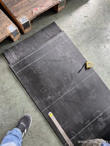
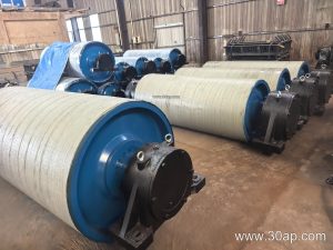
Pulley lagging is the rubber, ceramic, or composite layer bonded to the shell of a conveyor pulley to raise friction between the drum and the conveyor belt. Without it, a bare steel shell can slip once the belt is wet, dusty, or heavily loaded, and slip means heat, wear, and lost throughput. A quarry conveyor feeding a primary crusher or a power plant coal handling line depends on that grip every shift, and the lagging is the part that quietly makes it happen.
In practice, the term covers both the material and the process. Buyers often ask for pulley lagging by surface form, hardness, and thickness, then leave the bonding method to the workshop. Both halves matter, because a good rubber compound applied badly will peel long before a modest compound applied well.
How the Lagging Is Built
Most lagging starts as a rubber sheet or a molded strip. It is applied in one of three main ways.
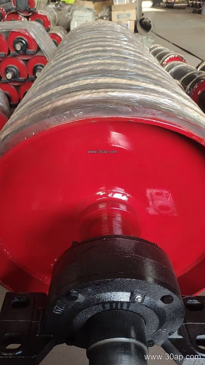
- Hot vulcanized lagging is cured onto the shell under heat and pressure, forming a chemical bond. It is the most durable option and the usual choice for drive pulleys on heavy-duty mining conveyor belts.
- Cold bonded lagging uses an adhesive system at ambient temperature. It suits field repairs and smaller pulleys where a press is not available.
- Cast or sprayed lagging is poured or sprayed into a mold around the shell, often with grooves formed in place.
Ceramic lagging takes a different route: small alumina tiles are embedded in a rubber matrix, and the tile tips sit slightly proud of the rubber. The rubber flexes and grips, while the ceramic provides wear resistance and helps shed water through the channels between tiles.
Surface Forms and What They Suit
Plain or flat lagging is the default for many tail and bend pulleys, where the goal is protection rather than traction. Diamond pattern and herringbone pattern lagging add grooves that let water and fines escape from the contact zone, which improves grip on wet belts. Ceramic lagging is chosen where abrasive slurry or sharp aggregate would chew through plain rubber.
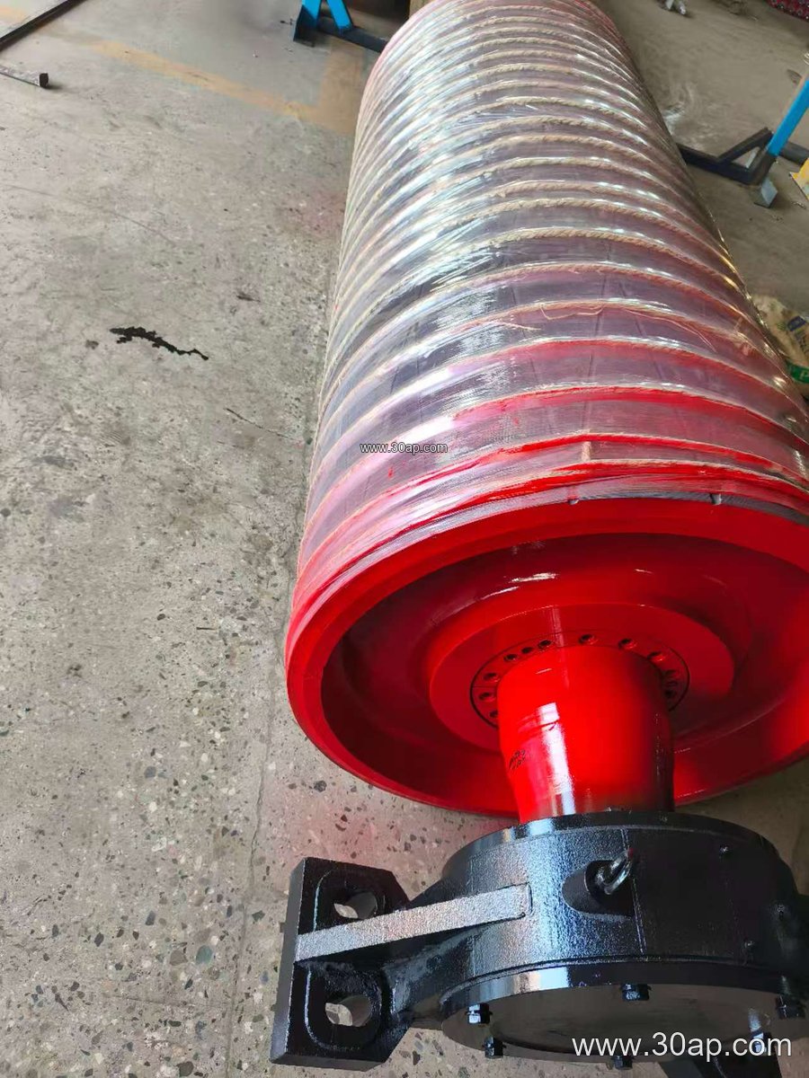
Thickness is usually specified in the range of 8, 10, 12, 15, or 20 mm. A thicker layer gives more wear life and more cushioning, but it also changes the effective diameter, so the pulley and belt tensioning arrangement should be designed with the lagging thickness in mind. Hardness is typically quoted in Shore A, and softer compounds grip better while harder ones resist abrasion.
Where It Is Used
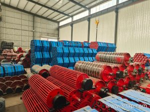
The drive pulley does the pulling, so it almost always carries lagging. A tail pulley at the loading point may use it too, partly for grip and partly to protect the shell from impact and grit. Bend and take-up pulleys usually receive a plain rubber layer for wear protection.
The application matters as much as the position. In a limestone quarry, wet fines and sharp rock push toward ceramic or grooved rubber. In a cement plant, hot clinker dust can degrade some compounds, so the lagging and the heat resistant conveyor belt above it should be matched to the temperature. In a coal washing plant, oil and fine coal slurry favor oil resistant grades. Port bulk terminals handling iron ore or copper ore concentrate often run large pulleys with heavy-duty lagging that resists both abrasion and moisture.
One caution: lagging on a drive pulley and lagging on a tail pulley are not interchangeable choices. The drive needs traction; the tail often needs protection. Specify each position on its own.
Common Pulley and Lagging Reference Data
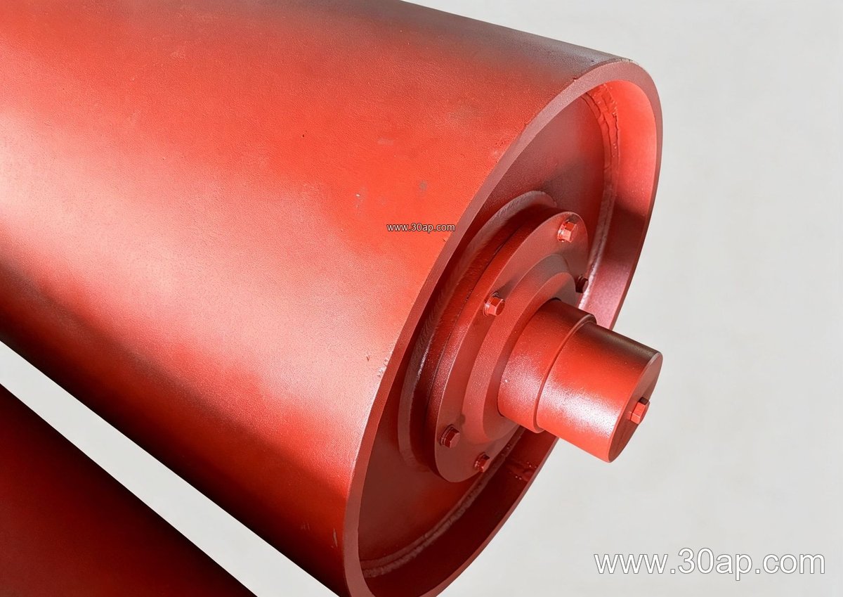
The table below gives typical starting points, not fixed rules. Final values depend on belt tension, torque, and the pulley manufacturer’s design.
| Item | Typical range |
|---|---|
| Belt width | B400, B500, B650, B800, B1000, B1200, B1400, B1600, B1800, B2000 |
| Pulley diameter | Ø200, Ø250, Ø315, Ø400, Ø500, Ø630, Ø800, Ø1000, Ø1250 |
| Lagging thickness | 8, 10, 12, 15, 20 mm |
| Shell face width | B400 about 500 mm; B800 about 950 mm; B1200 about 1400 mm; B1600 about 1800 mm |
| Shaft diameter | Ø50 to Ø200, set by torque and load |
A B1200 × Ø1000 drive pulley and a B800 × Ø500 tail pulley are both common combinations, and neither width locks the diameter. Shaft size follows the torque calculation, never the belt width alone.
What a Buyer Should Check
- Confirm the pulley position and duty before choosing a surface form.
- Ask for the compound and hardness, not just the color.
- State the bonding method you expect, especially for field installation.
- Check that the lagging thickness is included in the pulley diameter and belt take-up design.
- Match the lagging to the belt: an abrasion resistant conveyor belt and a ceramic-lagged drive pulley belong together in a hard rock circuit, while a food grade conveyor belt calls for a different, cleaner compound.
- Plan inspection intervals; worn grooves and embedded stone are easier to fix early.
Get the lagging right and the conveyor pulley, the idler roller frames, and the conveyor bracket assemblies all last longer, because a belt that tracks and grips properly stops punishing everything around it.