What a Conveyor Leg Does on a Belt System
A conveyor leg is the vertical support element that carries the weight of a conveyor frame, its idler rollers, and the loaded belt down to the floor or foundation. In a typical troughing section, the leg works together with a cross beam and a conveyor bracket to hold the idlers at the required angle. Without properly sized legs, the frame sags, the belt misaligns, and the whole transfer line becomes a maintenance problem. This article explains how these supports are built, where they are used, and what to check before ordering.
Construction and Common Materials
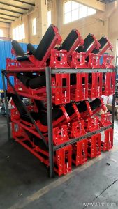
Most legs are fabricated from structural steel. Angle steel and channel steel are the usual choices for light and medium frames, while folded steel plate is often selected for heavier loads or for legs that need a closed profile. The leg is normally bolted to the cross beam and anchored to the ground through a base plate with bolt holes. Height, hole spacing, and base dimensions are determined by the belt width, the trough angle, and the height of the discharge point, so they should always be confirmed against the general arrangement drawing.
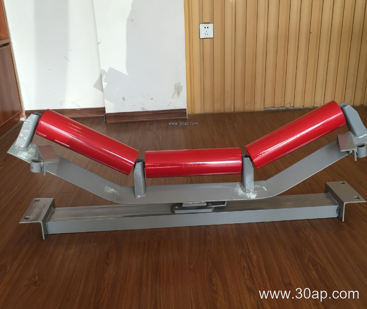
- Angle steel legs: simple fabrication, common on lighter quarry and aggregate lines
- Channel steel legs: higher bending resistance for wider frames
- Folded plate legs: clean appearance and good stiffness for heavy-duty sections
Where These Supports Are Used
These supports appear wherever a belt conveyor needs a stable frame above ground level. In a limestone quarry, legs carry the troughing sections that feed a crusher conveyor belt. In a coal handling plant or a power plant coal yard, they support long runs of flame retardant conveyor belt. In a cement plant, they hold the clinker and raw meal lines, while in a sand and gravel yard they keep the screening and stockpile conveyors level and aligned.
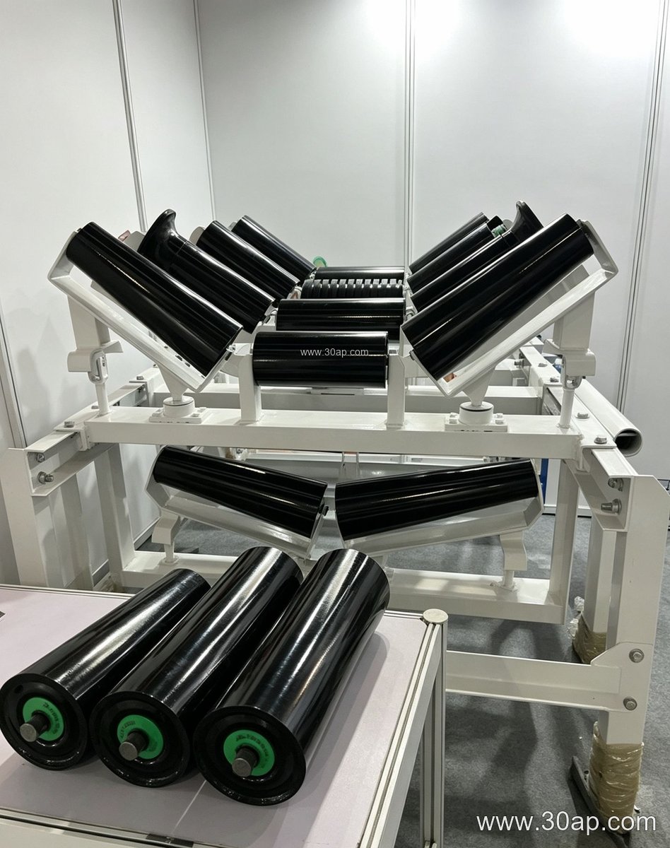
The support itself does not touch the material, but its accuracy affects everything above it. A leg that is out of plumb or set at the wrong height will tilt the frame, change the trough angle, and put uneven load on the conveyor pulley and the idler roller bearings.
Types and Typical Parameter Ranges
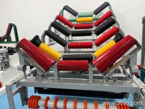
Supports are usually grouped by their position and function. Troughing support legs, transition legs, and return legs are the most common forms. Adjustable legs allow the frame height or trough angle to be corrected on site, while fixed legs are simpler and cheaper once the geometry is final. The table below shows common reference ranges; actual values follow the design drawing.
| Item | Common Reference Range | Notes |
|---|---|---|
| Belt width B | B500, B650, B800, B1000, B1200, B1400, B1600, B1800, B2000, B2200 | Leg height and beam length increase with belt width |
| Trough angle | 20°, 30°, 35°, 45° | Adjustable legs can be set within this range |
| Idler diameter | Ø89, Ø108, Ø133, Ø159, Ø194 | Selected by load and belt speed, not by width alone |
| Typical combination | B800, 35°, Ø108 | Example only, not a fixed rule |
| Material | Angle steel, channel steel, folded plate | Depends on load and frame design |
Do not assume that one belt width can only match one trough angle or one roller diameter. A B1200 frame may run at 35° or 45°, and the idler size is decided by the load calculation. Installation hole spacing and cross beam length vary with width and angle, so they must be taken from the drawing rather than from a catalogue table.
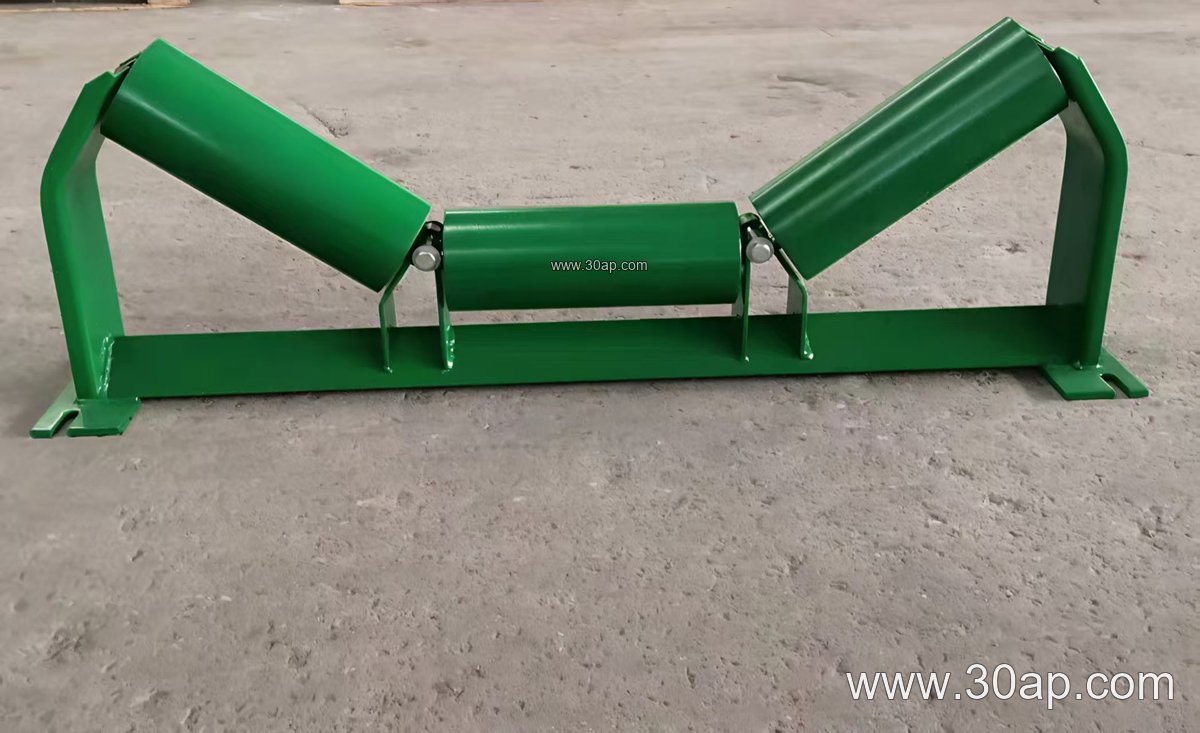
Buyer Checklist Before Ordering
- Confirm belt width and trough angle, for example B650, 30°, Ø89 for a small aggregate line.
- State whether fixed or adjustable height is required, and the adjustment range.
- Provide the frame drawing so hole spacing and base plate dimensions match.
- Check the surface treatment, since dusty or wet sites need adequate corrosion protection.
- Confirm the interface with the conveyor bracket and cross beam, not just the leg itself.
- Match the leg height to the actual ground level and foundation bolts on site.
Installation and Maintenance Notes
Set legs on a level foundation and check plumb before tightening anchor bolts. Align each frame section so the belt runs centrally over the idler roller; a small error at the leg becomes a large tracking problem over a long run. Inspect base plates and bolt connections regularly, especially in coal mining conveyor belt systems where vibration and dust are constant. Replace bent or corroded legs promptly, because a single weak support can overload the neighbouring frame and the conveyor pulley at the drive end.
For heavy-duty mining conveyor belt installations, the support design should be reviewed together with the belt tension and the frame span. A well-matched support structure keeps the belt, idlers, and pulleys working as one system instead of a collection of parts.