What a Drive Rubber Lagged Pulley Does
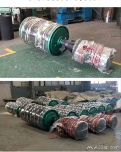
A drive rubber lagged pulley is the powered drum at the head of a belt conveyor that transfers torque from the gearbox to the conveyor belt. The rubber lagging is the key detail: it raises the friction coefficient between drum and belt, which lets the drive transmit more pull without excessive belt tension. In a quarry, a coal washing plant or a cement clinker line, that extra grip often decides whether a conveyor can start fully loaded without slipping.
The same component is also called a rubber lagged head pulley or lagged drive drum. It should not be confused with a tail pulley, a bend pulley or a take-up pulley; those serve different positions and duties, and only the drive pulley carries the main motor torque.
Construction and Surface Options
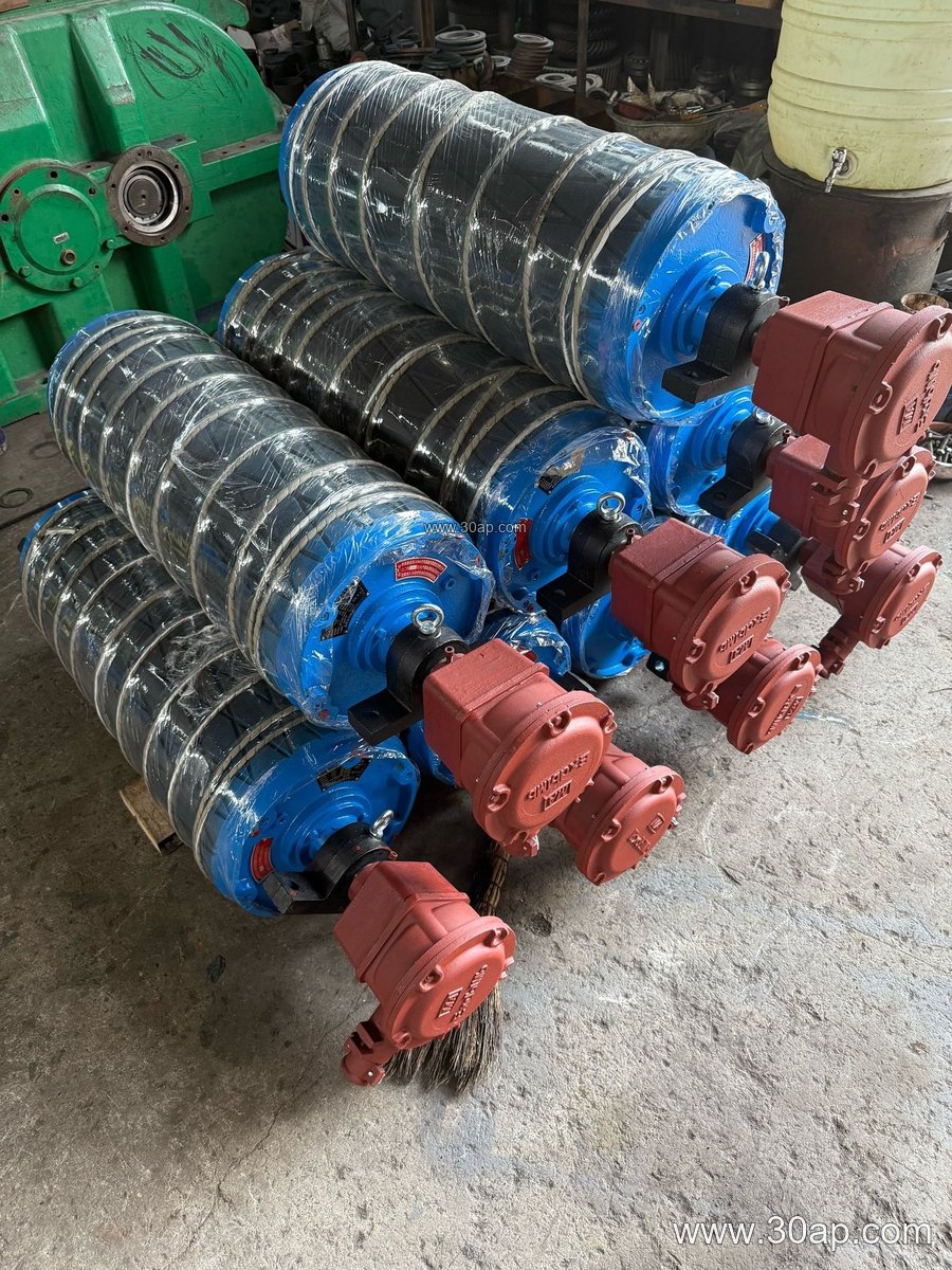
A typical unit combines a steel shell, welded end discs, a shaft, bearing housings and a lagged surface. Lagging may be applied by hot vulcanization, cold bonding or casting directly onto the shell. Surface patterns are chosen to match conditions:
- Plain rubber lagging for general dry bulk duty
- Diamond lagging to help shed water and fines
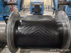
- Herringbone lagging for better self-cleaning on wet belts
- Ceramic lagging where abrasive grit and high slip risk are present
Common lagging thicknesses are 8, 10, 12, 15 and 20 mm. Thicker rubber lasts longer under heavy slip but adds weight and cost. The shell is usually wider than the belt; for example, a B800 belt commonly runs on a shell around 950 mm wide, and a B1200 belt on roughly 1400 mm.
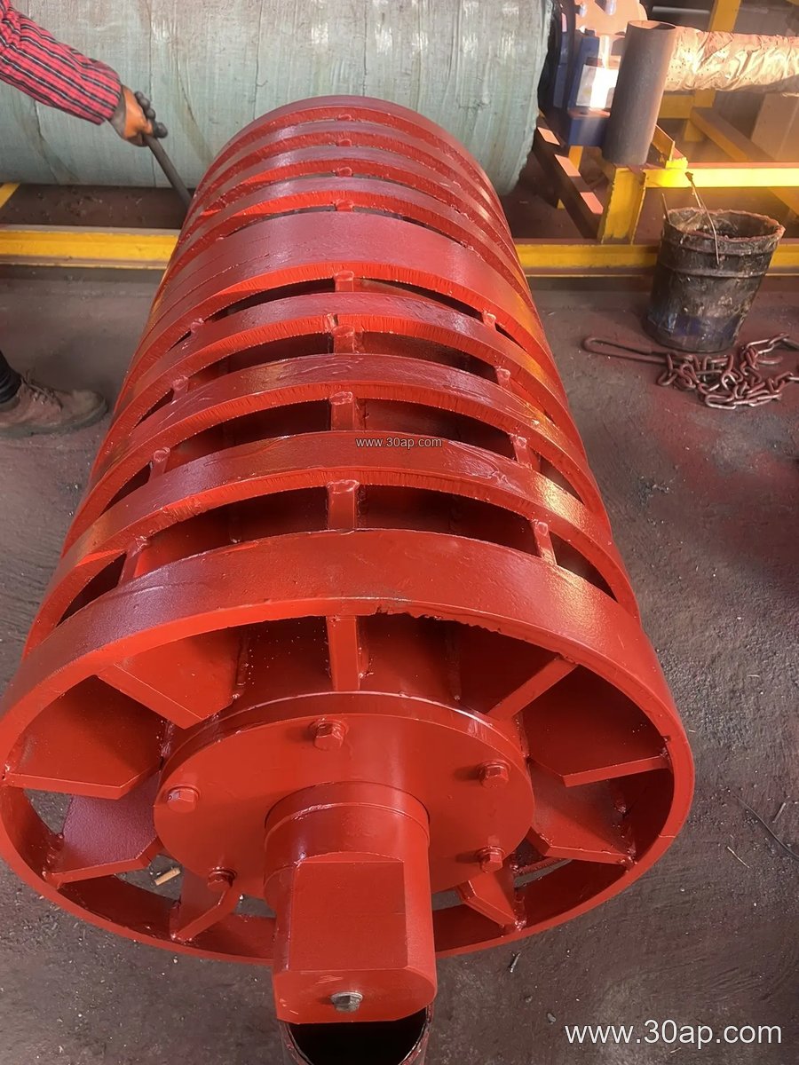
Where It Fits in the Plant
Drive rubber lagged pulleys appear wherever a belt must be positively driven. In an iron ore or copper mine, the primary haulage conveyor may use a large drum with ceramic or diamond lagging. In a power plant coal handling system, a diamond pattern helps in damp conditions. Aggregate plants, fertilizer granulation lines and tunnel spoil conveyors also rely on lagged drive drums to keep the belt tracking under load.
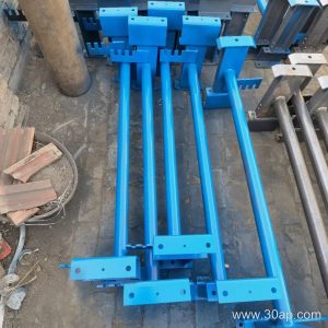
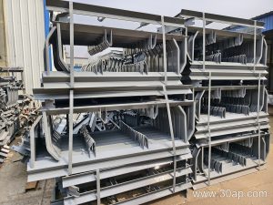
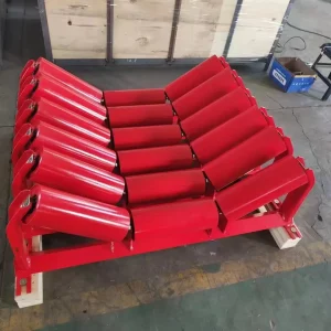
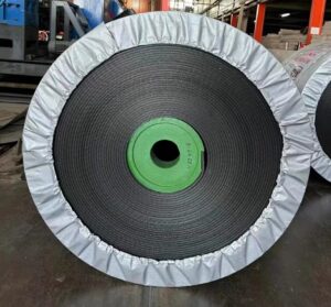
The pulley works together with the conveyor belt, conveyor idler rollers and conveyor brackets. Misalignment at any of these points shows up first as edge wear or slip at the drive drum, so installation accuracy matters as much as the lagging itself.
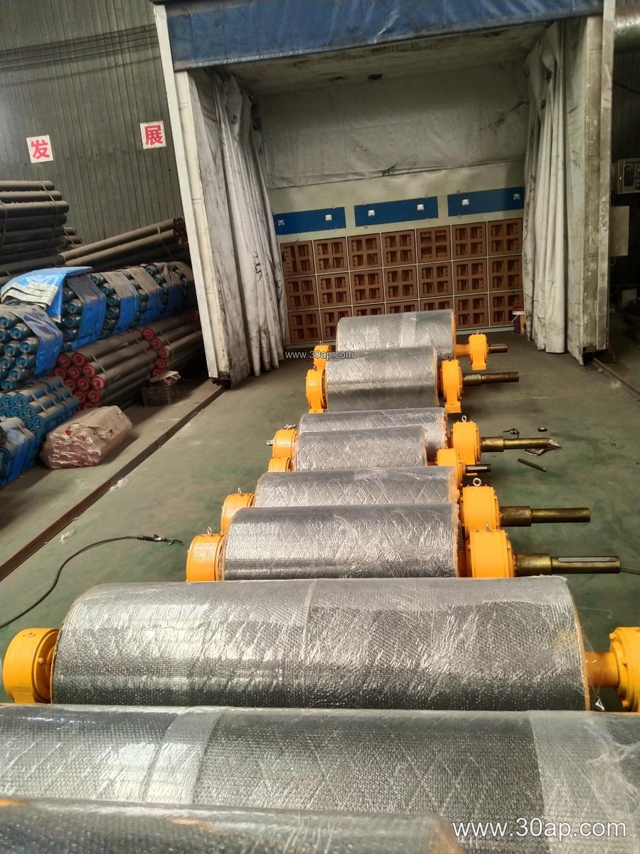
Reference Dimensions for Early Planning
The values below are typical reference ranges, not fixed rules. Final diameter and shaft size follow torque, belt tension and load calculations.
| Belt width | Typical shell width | Common diameter range | Lagging thickness |
|---|---|---|---|
| B500 | about 600 mm | Ø250 to Ø400 | 8 to 12 mm |
| B650 | about 750 mm | Ø315 to Ø500 | 8 to 12 mm |
| B800 | about 950 mm | Ø400 to Ø630 | 10 to 15 mm |
| B1000 | about 1150 mm | Ø500 to Ø800 | 10 to 15 mm |
| B1200 | about 1400 mm | Ø630 to Ø1000 | 12 to 20 mm |
| B1400 | about 1600 mm | Ø800 to Ø1250 | 12 to 20 mm |
| B1600 | about 1800 mm | Ø1000 to Ø1400 | 15 to 20 mm |
Shaft diameters commonly seen include Ø80, Ø100, Ø120, Ø140, Ø160 and Ø180, but the shaft is sized from torque and bearing load, never from belt width alone. A B1200 × Ø1000 drive drum and a B800 × Ø500 unit may both be reasonable in different layouts.
What Buyers Should Check
Confirm the actual belt width, belt speed, motor power and starting method before ordering. Ask how the lagging is bonded and whether grooves suit wet or dry material. Check bearing type, shaft end dimensions and the interface with the conveyor bracket. For a replacement, measure the existing drum, not just the belt. Spare lagging sheets and a wear inspection schedule extend service life, especially in abrasive sand and gravel service.