What the Ø159 Conveyor Idler Is
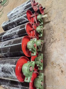
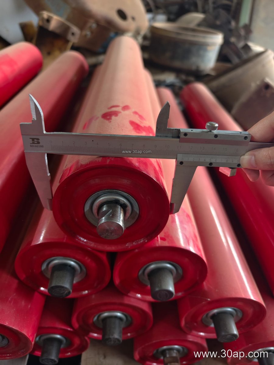
The Ø159 conveyor idler is a heavy-series carrying roller with a nominal shell diameter of 159 mm. It sits under the belt on a troughed or return station and supports the load as material moves from one transfer point to the next. In plant language it is often called a 159 mm idler roller or a Ø159 carrying roller; those names describe the same component, not a different product family. Compared with a drive pulley, tail pulley or bend pulley, the idler does not transmit torque — it rotates freely and simply carries the belt.
Because of its larger diameter, this size is usually chosen for wide belts, high belt speeds and heavy bulk streams. You will see it in iron ore terminals, copper concentrator plants, limestone quarries and power station coal yards where a smaller roller would spin too fast and wear too quickly.
How the Roller Is Built
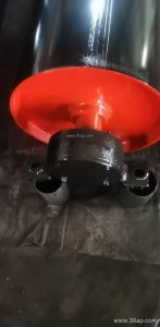
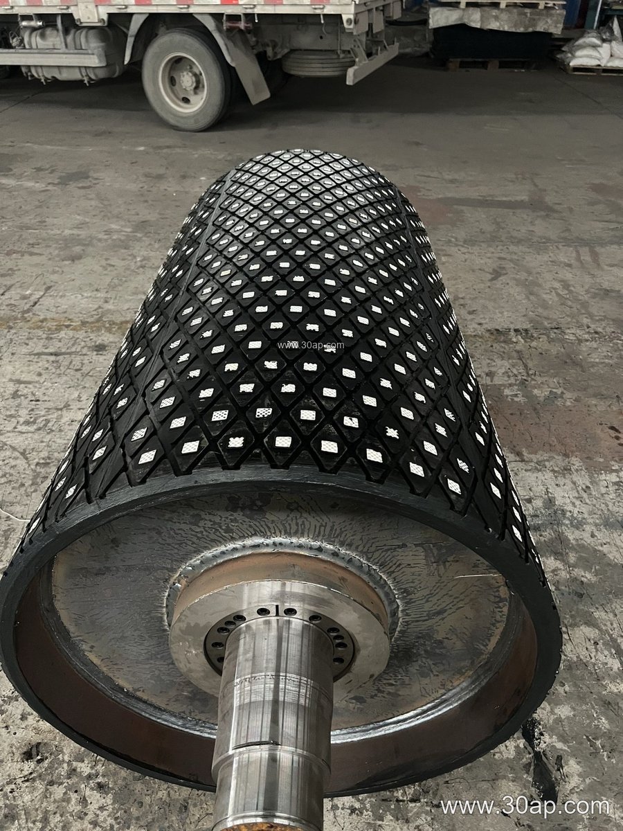
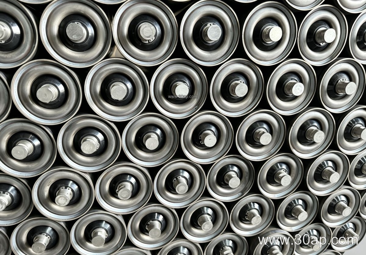
A typical unit combines a steel tube shell, pressed end caps, a shaft, and sealed bearings. Common bearing sizes used in this diameter class include 6308 and 6310, though the final choice depends on load and speed rather than on diameter alone. The shell may be plain steel, nylon-coated, ceramic-lined or fitted with rubber rings for impact absorption.
- Shell: welded steel tube, machined at both ends
- Bearing housing: pressed or cast, with labyrinth or contact seals
- Shaft: through-shaft or stub-shaft design, flattened ends for bracket mounting
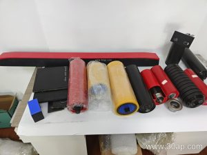
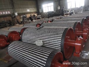
- Surface options: plain, rubber disc, ceramic tile
Sealing quality matters more than most buyers expect. In a wash plant or a coastal port, fine dust and moisture attack bearings long before the shell wears out. A well-sealed Ø159 idler roller usually outlasts a cheaper unit by a wide margin.
Where It Fits on the Conveyor
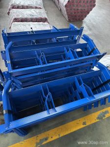
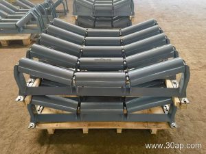
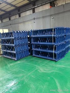
Three-roll troughing sets are the most common arrangement for this diameter. The centre roll and the two side rolls form a trough that keeps bulk material centred on the belt. Trough angles of 30, 35 and 45 degrees are all used; a 45-degree set gives a deeper trough for sticky or high-capacity loads, while 30 to 35 degrees suits general aggregate duty.
Roll length varies with belt width, trough angle and roll position. The following values are common examples only and should be confirmed by design:
| Belt width | Typical roll length (three-roll trough) |
|---|---|
| B800 | about 315 mm |
| B1000 | about 380 mm |
| B1200 | about 465 mm |
| B1400 | about 530 mm |
| B1600 | about 600 mm |
| B1800 | about 670 mm |
| B2000 | about 750 mm |
Side rolls and centre rolls can differ in length within the same station, so the table is a starting reference, not a fixed match. The conveyor bracket and frame spacing must also agree with the shaft ends.
Return and Impact Positions
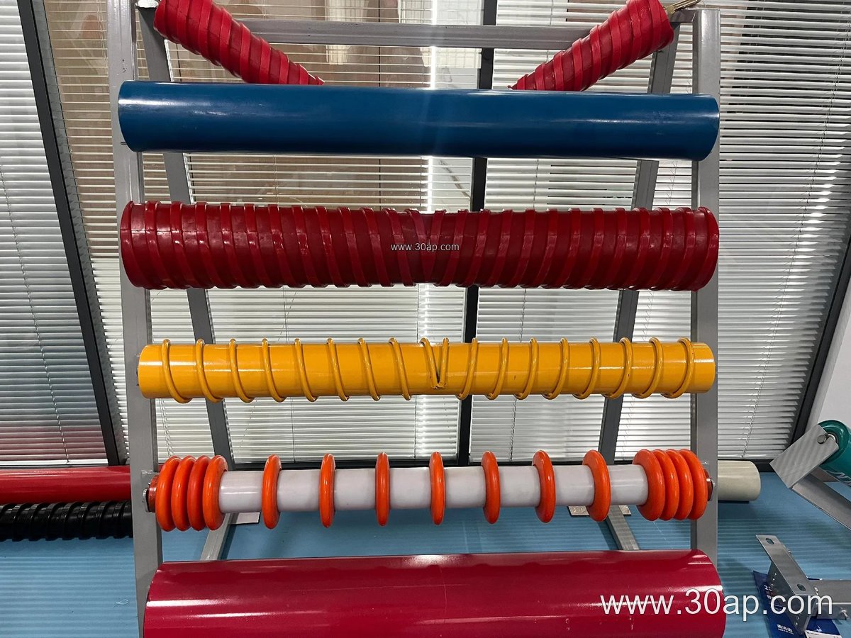
On the return strand, a Ø159 roller may appear as a flat return roll or as part of a V-shaped return set that helps the belt track straight. At loading points, rubber-disc impact rolls are used to cushion falling rock. These are related positions rather than replacements for the carrying roll — each station has its own duty.
Self-aligning versions with tapered ends are another variant worth considering on long flights where belt wander is a problem. They correct misalignment by turning slightly against the belt edge.
Matching the Belt and the Duty
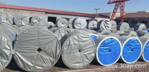
The idler never works alone. A heavy-duty mining conveyor belt running at high tension needs rollers that can take the load without excessive deflection. On a coal mining conveyor belt with flame retardant covers, the roller surface should also avoid generating static, so anti-static and conductive options are sometimes requested. In a cement plant, heat resistant conveyor belt sections near the kiln discharge may call for heat-tolerant bearing grease and careful roller placement.
For general guidance: match roller diameter to belt width and speed, match bearing class to load, and match surface to the material. Do not assume that one belt width can only use one pulley diameter, and do not derive a shaft size from belt width alone — those values come from the conveyor design.
Buyer Checklist
- Confirm shell diameter, roll length and shaft end type against the existing frame
- State bearing size or load requirement, not just the roller diameter
- Choose the surface: plain steel, rubber ring, nylon or ceramic
- Check seal type for dusty, wet or corrosive sites
- Ask for rotation test and radial runout data where available
Spare rollers stored on site should be kept dry and upright. A rusty shaft or a deformed end cap will cause installation trouble even if the shell itself is sound.