What a Non-Standard Conveyor Bracket Is
A non-standard conveyor bracket is a support component made to fit a conveyor geometry that off-the-shelf brackets cannot handle. In a quarry, a cement plant or a tunnel spoil line, the structure rarely matches a catalogue drawing exactly. The frame may be skewed, the transition zone short, or the belt path routed around existing equipment. In these cases the bracket is fabricated to the project, not picked from a stock list.
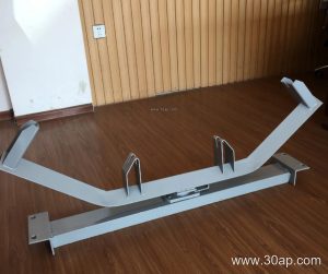
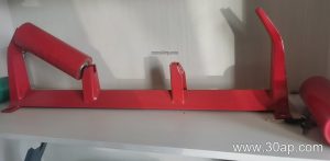
It is still a bracket in the ordinary sense: it holds and positions a conveyor idler roller, carries the belt load into the frame, and keeps spacing stable along the run. What changes is that its mounting holes, beam length, angle and height are set by the layout rather than by a standard series. The same fabricated approach is often used where a conveyor pulley or a bend section needs a support that clears nearby steelwork.
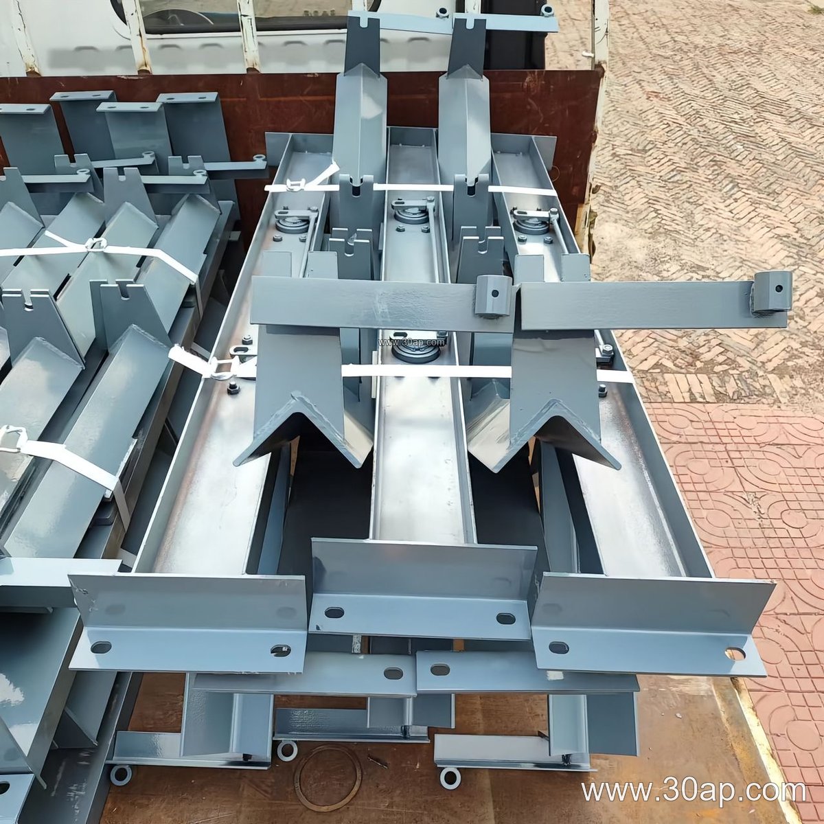
How the Bracket Is Built
Most non-standard brackets are welded from angle steel, channel steel or folded plate. The material choice follows the duty: a light sand and gravel line may use folded plate, while a primary crushing discharge or a coal handling plant usually calls for heavier channel sections. Common build details include:
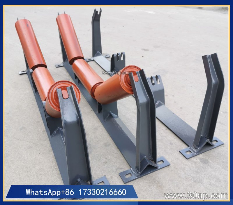
- Base plate drilled to the actual frame hole pattern
- Inclined arms set to the required trough angle
- Reinforcing ribs at the weld between arm and base
- Slotted holes or shim packs where field adjustment is expected
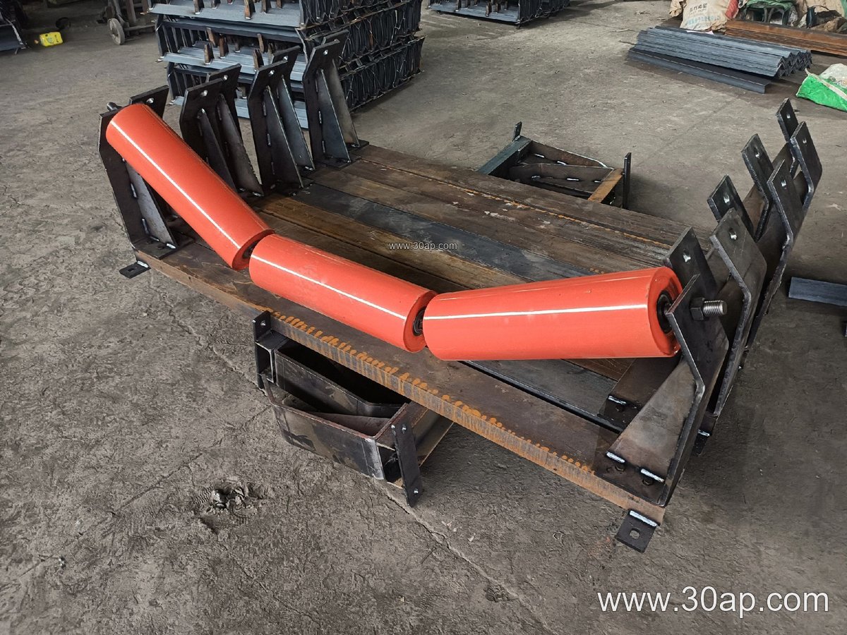
Because the part is project-specific, the drawing should state the belt width, the trough angle and the roller diameter together. A typical combination might read B800, 35 degrees, Ø108, or B1200, 45 degrees, Ø133. These are common references, not fixed rules. Hole spacing and crossbeam length change with belt width and trough angle, so they are confirmed per design rather than assumed.
Where It Fits on the Conveyor
The bracket appears wherever the standard frame cannot be used as drawn. In a limestone mine, a transition bracket may be needed between the tail pulley and the first carrying idler, where the belt moves from flat to troughed. In a power plant coal yard, a non-standard return bracket might be fabricated to suit a modified frame after a chute upgrade. Similar work turns up in sinter plants, fertilizer handling and grain silos.
It is useful to separate this part from related hardware. A carrying bracket positions the troughing idlers; a return bracket holds the lower rollers; a V-type return bracket is a different sub-type and is not a substitute. A self-aligning bracket has its own function. None of these should be treated as interchangeable with a made-to-fit bracket, because the custom part is defined by its fit to the structure.
Specification Points Buyers Should Confirm
A clear enquiry saves rework. The table below lists the information that usually drives fabrication.
| Item | Typical reference | Why it matters |
|---|---|---|
| Belt width | B500 to B2200 | Sets bracket span and roller length |
| Trough angle | 20, 30, 35 or 45 degrees | Fixes arm angle; adjustable versions allow change on site |
| Roller diameter | Ø89, Ø108, Ø133, Ø159, Ø194 | Determines cradle height and hole position |
| Material | Angle, channel or folded plate | Matches load and environment |
| Mounting | Fixed or slotted | Allows field alignment where needed |
Buyers should also ask whether the bracket is fixed or adjustable. An adjustable type can be set between common trough angles, which helps when a plant plans to change belt loading later. Forward-leaning brackets, usually around 1.5 to 2 degrees, are a separate design choice and should be requested explicitly if wanted.
Practical Notes for Selection and Maintenance
Match the bracket to the actual frame, not to a nominal drawing. Send the hole pattern, the frame channel size and the roller position. State the environment: dust in a crushing circuit, moisture in a wash plant, or heat near a sinter cooler all affect the steel and coating choice. On installation, check that the bracket sits square to the belt centreline; a twisted bracket will misalign the idler roller and wear the conveyor belt edge. During maintenance, inspect welds and bolt tightness after the first weeks of running, then at routine stops. Replace a deformed bracket rather than bending it back, since a straightened part may no longer hold the correct angle.
Used with care, a made-to-fit bracket keeps a conveyor running true where standard parts will not fit, and it lets the idler roller, belt and pulley work together as the layout intended.