What a Motor-Driven Pulley Actually Is
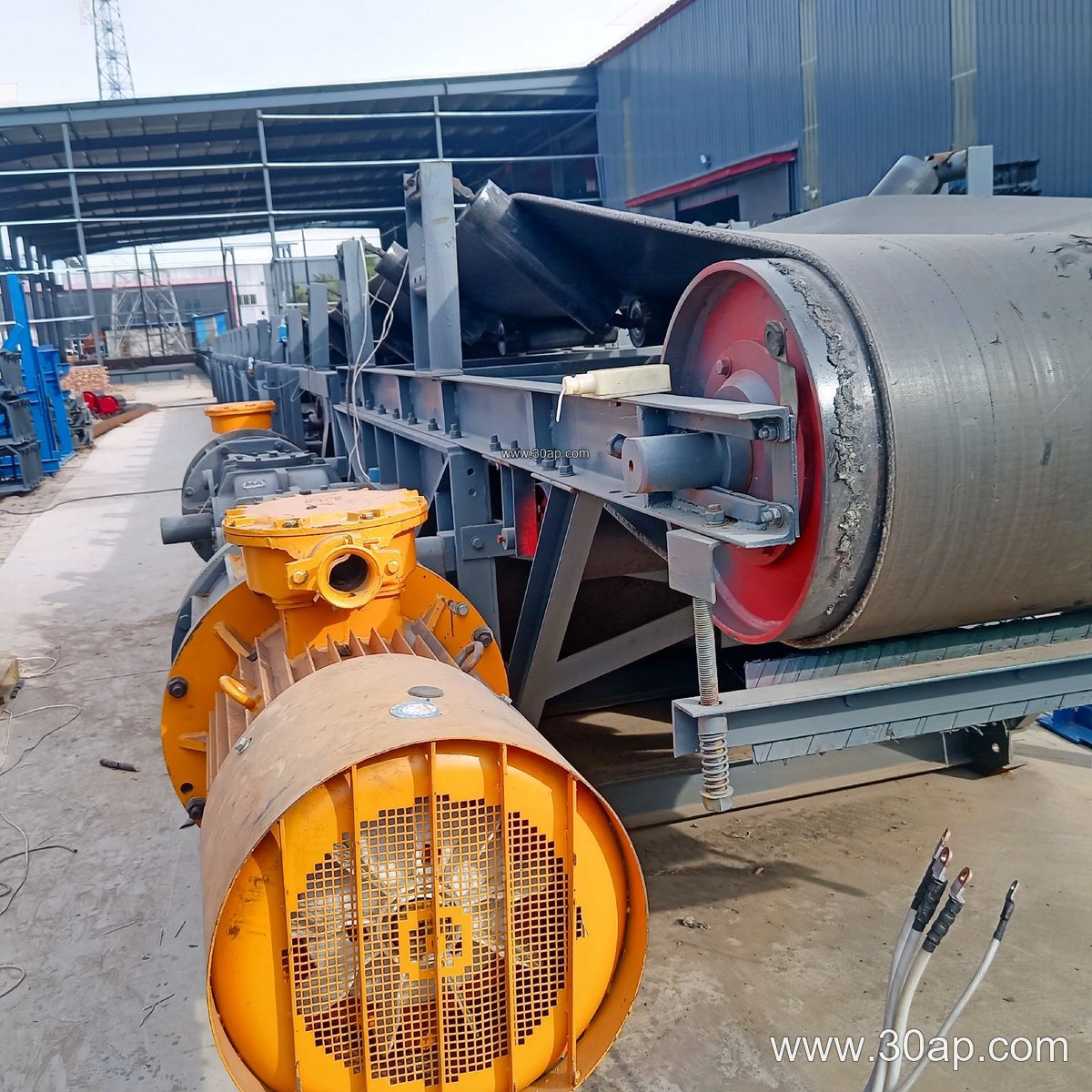
A motor-driven pulley is a conveyor pulley that contains its own drive motor and gear reduction inside the drum shell, so it turns the conveyor belt without an external gearbox, coupling, or drive shaft. In many plants this unit is simply called a motorized pulley or drum motor. It is a distinct product from a drive pulley that is turned by a separate motor through a gear reducer, and it must not be confused with tail pulleys, bend pulleys, or snub pulleys, which guide or tension the belt rather than power it.
The concept is compact: the belt rides on the shell, the internal motor produces torque, and the pulley surface transfers that torque to the conveyor belt. Because the drive is enclosed, the unit suits locations where space around the head end is tight or where exposed rotating parts are undesirable.
How the Unit Is Built
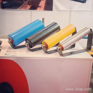
Inside the shell there is usually an electric motor, a multi-stage planetary or helical gear set, bearings, and a sealing arrangement. The shell is often covered with rubber lagging to raise friction between pulley and belt. Common surface forms include plain, cast rubber, cold-bonded rubber, hot-vulcanized rubber, diamond grooved lagging, herringbone lagging, and ceramic lagging, with lagging thickness typically 8, 10, 12, 15, or 20 mm depending on duty.
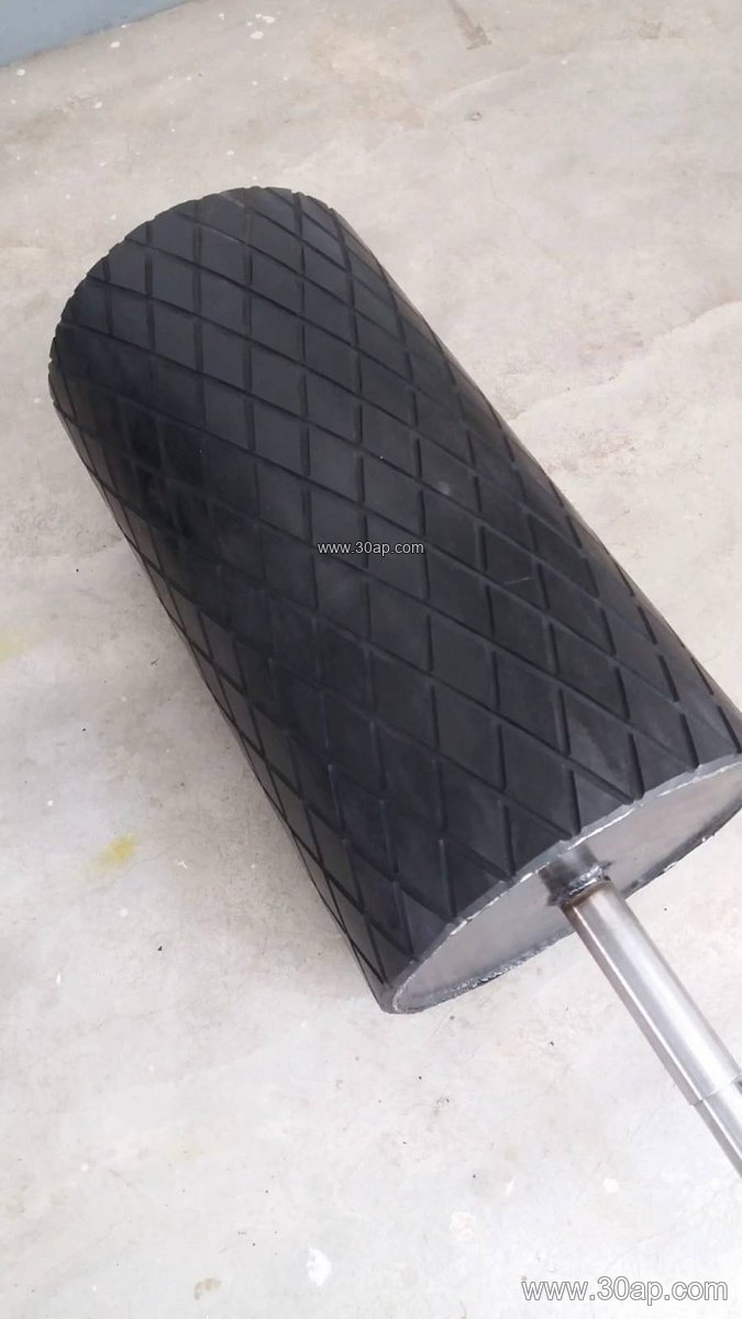
Shell diameter and face width are chosen together with belt width and belt tension. Face width is normally somewhat wider than the belt, for example B650 with roughly 750 mm face, B800 with about 950 mm, B1000 with about 1150 mm, and B1200 with about 1400 mm. Diameter might be Ø500 for a moderate belt and Ø800 or Ø1000 for a wider, heavier duty line. Shaft diameter, where a shaft end is used for mounting, is set by torque and load, commonly in the Ø50 to Ø200 mm range; it should not be picked from belt width alone.
Typical reference combinations
| Belt width | Approximate face width | Common diameter range | Lagging options |
|---|---|---|---|
| B500 | 600 mm | Ø250 to Ø400 | Plain, diamond rubber |
| B650 | 750 mm | Ø315 to Ø500 | Plain, cast rubber, ceramic |
| B800 | 950 mm | Ø400 to Ø630 | Diamond, herringbone |
| B1000 | 1150 mm | Ø500 to Ø800 | Hot-vulcanized rubber |
| B1200 | 1400 mm | Ø630 to Ø1000 | Ceramic, diamond lagging |
These figures are reference values, not fixed rules. A B1200 line may use Ø1000, and a B800 may use Ø500; the final choice follows belt tension, wrap angle, and starting torque.
Where It Fits on the Conveyor
The motor-driven pulley is most often placed at the head or discharge end, where it pulls the loaded belt. It also appears at intermediate drive points on long lines and on small mobile conveyors. In a quarry conveyor belt or a stone crushing line, the enclosed drive keeps dust away from the motor. In a coal mining conveyor belt or underground mining conveyor belt, flame retardant and anti-static belt grades are often used alongside the pulley, and the drum itself is sealed against fine coal dust.
For heavy abrasive duty, a high abrasion resistant conveyor belt pairs well with ceramic or diamond lagging to maintain grip. Where the belt carries hot clinker in a cement plant, a heat resistant conveyor belt is used, and the pulley lagging must tolerate the same temperature. In a power plant coal handling system, the motorized pulley can replace an exposed head drive and reduce the number of guarding points around the transfer tower. The drive also works with a pipe conveyor belt on curves and with a chevron conveyor belt where the raised cleats require careful pulley clearance.
Buyer Checklist
- Confirm the required belt pull and starting torque, not just the belt width.
- State the belt type and surface, such as EP conveyor belt, NN conveyor belt, steel cord conveyor belt, or multi-ply fabric core conveyor belt, because grip and tension differ.
- Choose lagging for the environment: ceramic for wet abrasive ore, diamond rubber for general bulk material, plain for light duty.
- Check that the drum fits the conveyor bracket and that the shaft or mounting arrangement matches the frame.
- Verify sealing and insulation class for dusty or washdown locations.
- Plan access for oil changes and bearing inspection, since service happens through the shaft end.
Matching the pulley to the belt and to the conveyor pulley layout, including idler roller spacing and take-up travel, avoids slip and premature lagging wear. A correctly sized motor-driven pulley delivers reliable drive in a compact package across mining, cement, power, and aggregate operations.