What a Motor-Driven Pulley Does
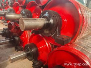
A motor-driven pulley is a conveyor pulley that carries its own drive unit inside the shell, so the drum itself powers the belt instead of an external gearbox and motor connected through a shaft. In plant layouts where space at the head end is tight, this self-contained design simplifies the frame, removes exposed couplings, and reduces the number of parts a maintenance team has to track. It is still a drive pulley in function, just packaged differently from a conventional head pulley with an external drive.
This article looks at how the unit is built, where it fits in bulk handling, and what to check before ordering. For belt selection, matching components such as a Rubber Conveyor Belt to the drum surface matters as much as the drum itself.
Construction and Internal Layout
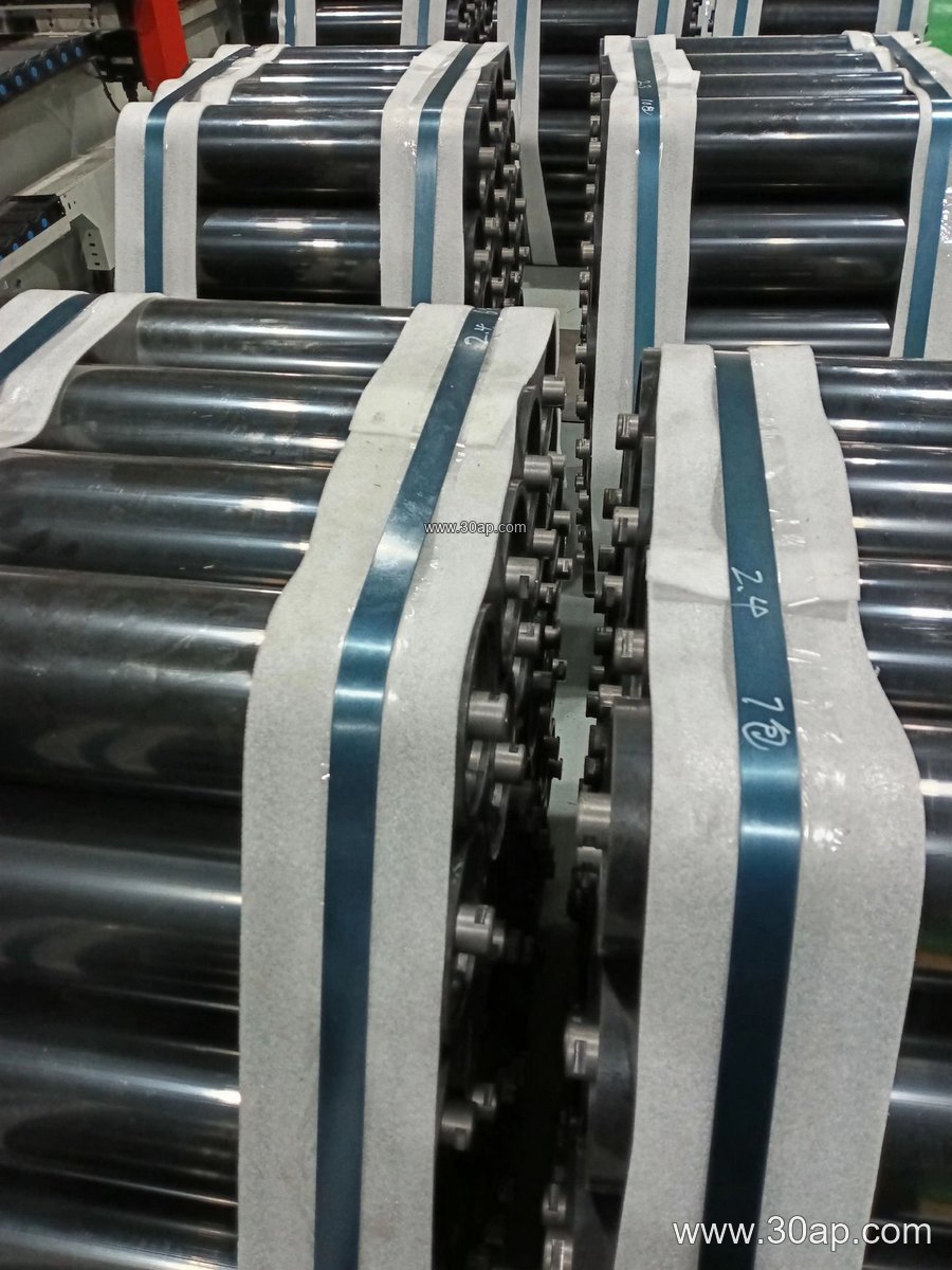
Inside the shell sits a geared motor, usually a planetary or helical arrangement, running in an oil bath. The shell is supported by bearings on a fixed shaft, and torque is transmitted through the gear stage directly to the drum. Because the drive is enclosed, the pulley needs a clean mounting position and reasonable access for oil checks.
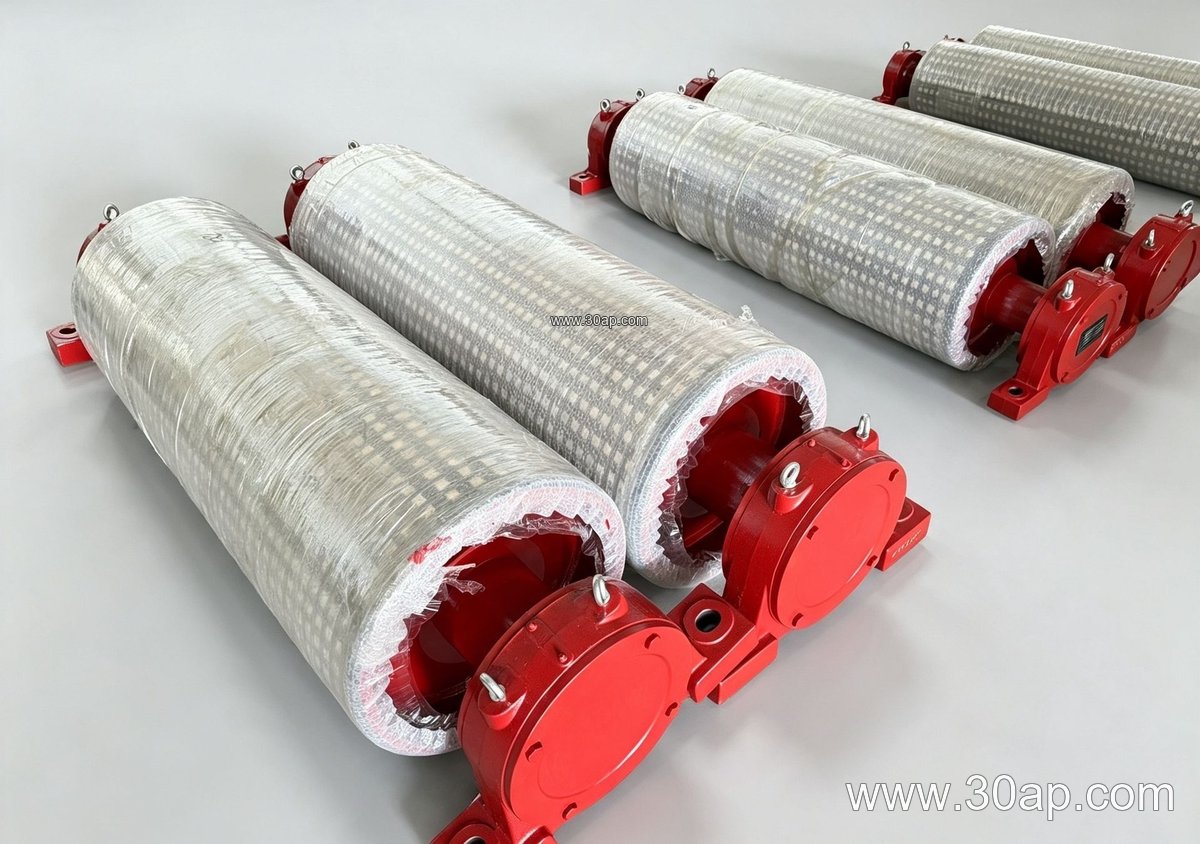
- Shell: seamless or rolled steel tube, machined at the ends
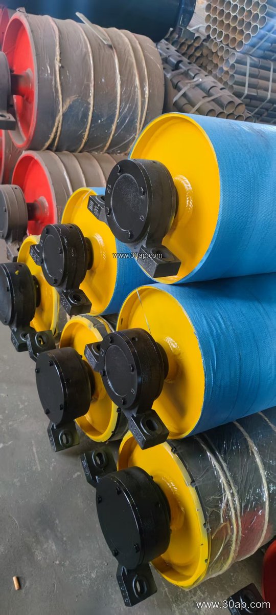
- Surface: plain, cast rubber, cold-bonded rubber, hot-vulcanized rubber, diamond, herringbone, or ceramic lagging
- Lagging thickness: commonly 8, 10, 12, 15, or 20 mm depending on grip and wear requirements
- Bearing housing: sealed for dusty service, with grease or oil lubrication as designed
The internal drive also means the shaft is not used to transmit torque to an outside gearbox, which changes how the bearing load and shaft diameter are calculated. Shaft sizes in common use include Ø50, Ø60, Ø70, Ø80, Ø90, Ø100, Ø120, Ø140, Ø160, Ø180, and Ø200, but the final value follows torque and load, not belt width alone.
Where It Fits in a Conveyor
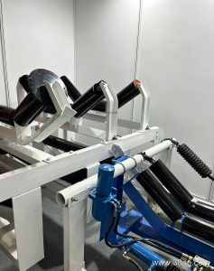
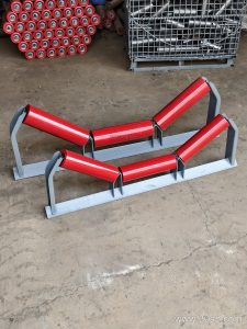
These pulleys are frequently used as the head or drive position on medium-capacity lines, and occasionally at intermediate or tensioning points where a compact drive is useful. They appear in quarry and aggregate plants, cement plants, power station coal handling, and port bulk terminals. A typical installation pairs the drum with a troughed belt, carrying idlers and return idlers, and a sturdy conveyor bracket to keep alignment under load.
Because the drive sits inside the drum, the pulley is usually the heaviest single component on the frame. The support structure must be designed for that mass plus belt tension, and the approach conveyor must deliver the belt to the drum at the correct wrap angle. On multi-pulley drives, the other positions may be a bend pulley or tail pulley with a separate drive, but those are different components and should not be treated as interchangeable with the motor-driven unit.
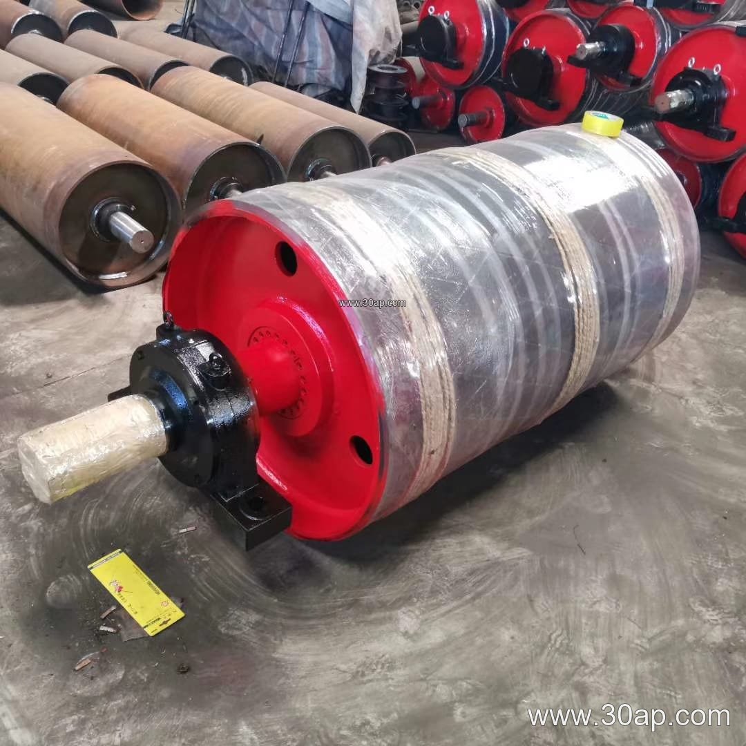
Sizes and Surface Options
Bandwidth and diameter are selected together with belt tension, speed, and the required grip. The table below gives common reference combinations; they are examples, not fixed rules, and a wider belt can be matched with more than one diameter.
| Belt width | Typical pulley face width | Example diameter |
|---|---|---|
| B500 | about 600 mm | Ø315 to Ø500 |
| B650 | about 750 mm | Ø400 to Ø630 |
| B800 | about 950 mm | Ø500 to Ø800 |
| B1000 | about 1150 mm | Ø630 to Ø1000 |
| B1200 | about 1400 mm | Ø800 to Ø1000 |
| B1400 | about 1600 mm | Ø800 to Ø1250 |
| B1600 | about 1800 mm | Ø1000 to Ø1400 |
| B1800 | about 2000 mm | Ø1250 to Ø1600 |
Surface choice depends on the material. Diamond or herringbone lagging helps shed water and fines, while ceramic lagging suits abrasive ore and rock. Where the belt is a Steel Cord Conveyor Belt under high tension, the drum shell and lagging must be checked for the resulting pressure.
Buyer Checklist
Before ordering, confirm the belt width, belt speed, required power, and the wrap angle at the drive. Ask for the shaft diameter calculation rather than accepting a size based only on belt width. Check the lagging type and thickness against the material being carried, and confirm the lubrication method and service interval.
- Duty: continuous or intermittent, and expected starts per hour
- Environment: dust, moisture, temperature, and whether the area is classified
- Belt: fabric core or steel cord, and whether a Flame Retardant Conveyor Belt is needed underground
- Mounting: access for oil changes and bearing inspection
- Spares: seal and bearing availability over the planned service life
During operation, watch for oil leaks, unusual noise, and belt tracking drift. A slipping or overheating drum usually points to lagging wear, overload, or a tension problem rather than a fault inside the gear unit. Keeping the belt and the drum surface clean extends the life of both.