What a Five-Roll Idler Bracket Does
A five-roll idler bracket is a support frame that carries five idler rollers under a loaded conveyor belt. Instead of the usual three-roll trough set, it spreads the belt across more contact points, so the same belt width can be guided through a deeper, smoother trough. In a quarry, a limestone mine or a cement plant, this helps keep coarse rock centered on the belt and reduces the chance of material spilling at transfer points.
The bracket is a structural part, not a roller and not a pulley. It works together with the idler roller, the conveyor belt and the conveyor pulley at the head and tail of the line. Drive pulleys, tail pulleys and bend pulleys each do a different job and are not interchangeable with this bracket.
How the Frame Is Built
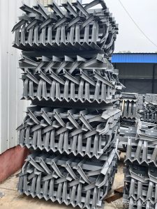
Most five-roll idler brackets are fabricated from angle steel, channel steel or folded steel plate. The crossbeam carries five mounting positions: a central flat or slightly angled roller and two rollers on each side. The side positions are set at a fixed trough angle or made adjustable, so maintenance crews can fine-tune the belt profile as the belt settles.
Common construction details include:
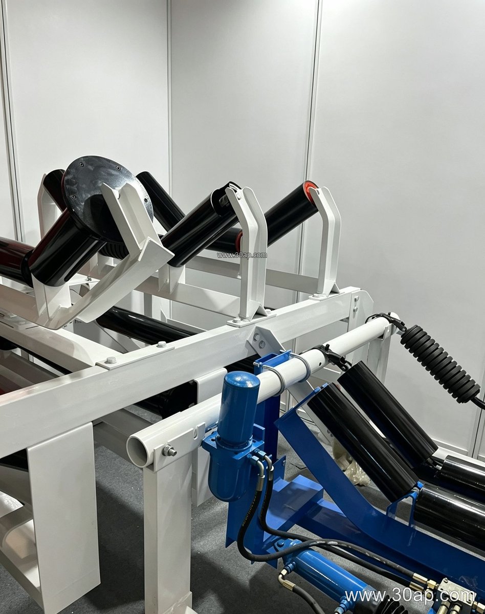
- Welded crossbeam with drilled mounting slots for each roller shaft
- Fixed or adjustable side arms for trough angle setting
- Bolt-on or pin-connected fixing to the conveyor stringer
- Optional forward tilt of about 1.5 to 2 degrees on the outer rolls for better belt tracking
Because the five rolls share the load, each roller carries less weight than in a three-roll arrangement. That can suit wide belts and heavy bulk material, where a heavy-duty mining conveyor belt runs over long distances.
Where It Fits on the Line
The bracket is usually installed on the carrying side, in the loading zone or along sections where the belt needs extra support. In a coal washing plant or a power plant coal yard, it may sit under the belt just after the feeding point, where impact and off-center loading are common. In a sand and gravel line or a crushing and screening circuit, it helps hold a wide trough under uneven stone flow.
It is not a substitute for a transition bracket, a return bracket or a self-aligning bracket. Those are separate support types with their own mounting positions. A five-roll set is chosen when the belt width and material load call for more contact points, not simply as a replacement for every other bracket on the conveyor.
Typical Reference Sizes
The table below shows common reference combinations. These are examples for orientation only; actual mounting hole spacing and crossbeam length are determined by belt width, trough angle and roller diameter.
| Belt width | Trough angle | Roller diameter | Typical use |
|---|---|---|---|
| B650 | 30 degrees | Ø89 | Small aggregate lines |
| B800 | 35 degrees | Ø108 | Sand and gravel, cement raw mix |
| B1000 | 35 degrees | Ø133 | Coal handling, ore transfer |
| B1200 | 45 degrees | Ø133 | Heavy bulk flow, crusher discharge |
| B1400 | 35 to 45 degrees | Ø159 | Large quarry and port lines |
| B1600 | 35 to 45 degrees | Ø159 or Ø194 | High-capacity bulk terminals |
Available trough angles commonly include 20, 30, 35 and 45 degrees, and adjustable brackets can be set between them. Roller diameters such as Ø89, Ø108, Ø133, Ø159 and Ø194 are common, but no single belt width is tied to one angle or one roller size.
Buyer Checklist
Before ordering, confirm the belt width, the required trough angle, the roller diameter and the shaft fixing method. Check whether the bracket must be fixed or adjustable, and whether the outer rolls need forward tilt. Measure the existing stringer hole spacing on site rather than assuming a standard value.
Also consider the belt type in service. A flame retardant conveyor belt in an underground coal mine, an abrasion resistant conveyor belt in a quarry, or a heat resistant conveyor belt near a sinter plant all place different demands on the support frame and its alignment. Matching the bracket to the real belt and load keeps the five-roll set doing its job.