What Conveyor Pulley Welding and Machining Really Involves
In a quarry, a coal wash plant, or a cement clinker line, the conveyor pulley is the part that keeps the belt moving and on track. The drive pulley transmits torque, the tail pulley keeps tension, and the bend pulley changes direction. Each one is a fabricated assembly, and its performance starts with two core processes: welding and machining. Get these right, and the pulley runs true for years. Get them wrong, and you will see belt mistracking, premature lagging wear, and shaft fatigue.
The Welding Stage Building the Pulley Body
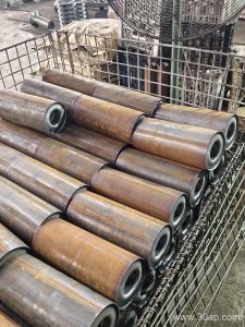
A typical conveyor pulley begins as a rolled steel shell, two end discs, and a central shaft. The shell is usually seamless pipe or rolled plate. Welding joins the end discs to the shell and the hub to the shaft. Submerged arc welding is common for long seams because it gives deep penetration with less distortion. For the hub-to-shaft connection, a shrink fit or keyed interference fit may be used before final welding. Welders must control heat input to avoid warping the shell. A warped shell will not machine round, and an out-of-round pulley will cause the conveyor belt to wander.
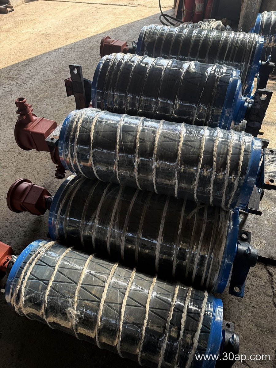
After welding, the assembly is stress-relieved in a furnace. This step reduces residual stresses that could later crack the weld or distort the machined surfaces. For pulleys that will see heavy impact, such as a tail pulley in a primary crushing circuit, a double-welded joint is often specified.
Machining for Concentricity and Balance
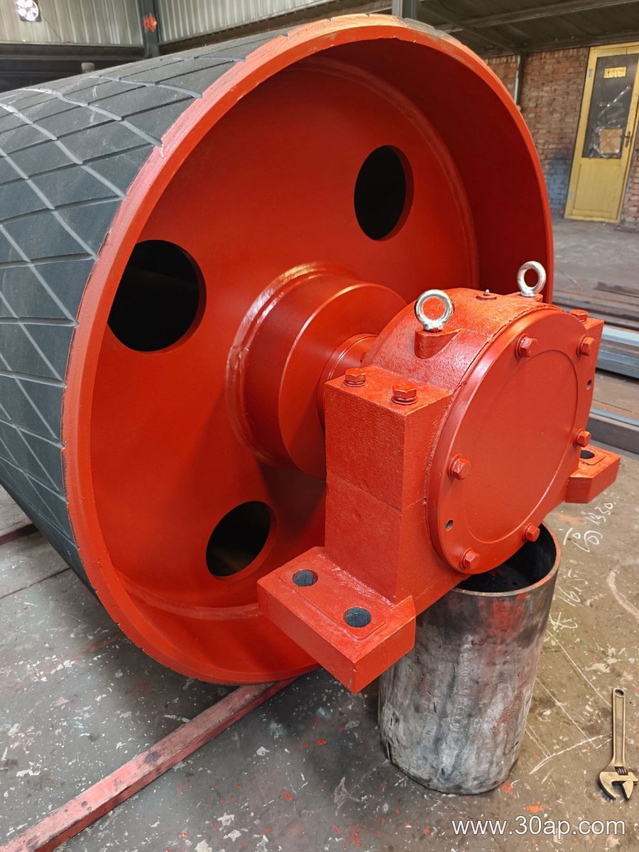
Machining turns the welded body into a precision component. The shaft ends are turned to fit bearings and couplings. The shell outside diameter is machined to accept lagging. The end faces are faced true so the pulley runs square with the shaft. A lathe with a long bed handles large diameters, while a portable line boring machine can machine the hub bore in place. Concentricity between the shaft and the shell is critical. If the shell runs out by more than a few tenths of a millimeter, the belt will track poorly and the lagging will wear unevenly.
Dynamic balancing follows machining. A pulley that spins at high speed with an unbalanced mass will vibrate, loosen bolts, and damage bearings. Balancing is especially important for head pulleys on high-capacity lines.
Surface Preparation for Lagging
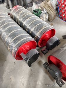
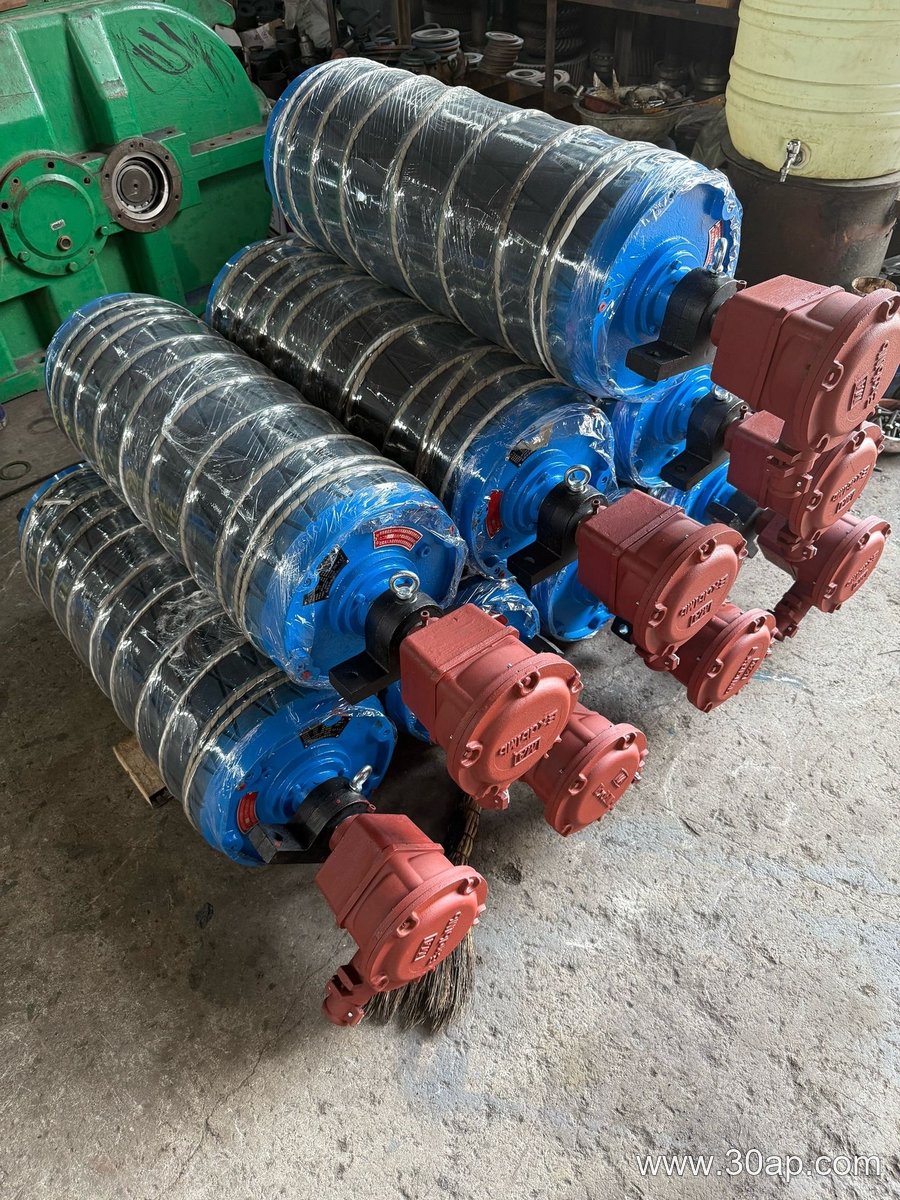
Most pulleys receive a rubber or ceramic lagging to increase friction and protect the shell. Common surface forms include plain, diamond, herringbone, and ceramic. Lagging thickness is often 8, 10, 12, 15, or 20 mm. Before bonding, the machined shell is grit-blasted and cleaned. Cold bonding or hot vulcanizing attaches the rubber. A poorly prepared surface leads to lagging separation, which is a common cause of unplanned downtime.
Typical Dimensions and Configurations
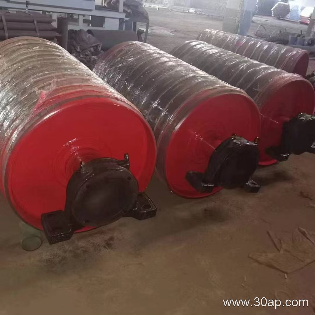
The table below shows common reference values, not a fixed rule. Diameter and shaft size are always determined by torque, belt tension, and load. A B1200 belt may use a head pulley with a diameter of Ø800 or Ø1000, depending on the drive design.
| Belt width | Common pulley face width | Reference diameter range | Typical shaft diameter range |
|---|---|---|---|
| B500 | ~600 mm | Ø200–Ø400 | Ø50–Ø80 |
| B800 | ~950 mm | Ø315–Ø630 | Ø70–Ø120 |
| B1000 | ~1150 mm | Ø400–Ø800 | Ø80–Ø140 |
| B1200 | ~1400 mm | Ø500–Ø1000 | Ø90–Ø160 |
| B1400 | ~1600 mm | Ø630–Ø1250 | Ø100–Ø180 |
| B1600 | ~1800 mm | Ø800–Ø1400 | Ø120–Ø200 |
These values are for general guidance. A drive pulley in a copper mine may need a larger shaft than a tail pulley of the same width because it carries higher torque. A bend pulley in a coal handling system may use a smaller diameter to save space.
Where These Pulleys Work
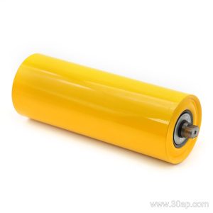
You will find welded and machined pulleys in almost every bulk material handling system. In a limestone quarry, the head pulley drives the primary conveyor. In a power plant coal yard, the tail pulley keeps the belt tensioned. In a sand and gravel plant, bend pulleys route the belt around a tripper. The idler roller and conveyor bracket work alongside the pulley, but they do not replace it. The pulley is the power and direction component.
What a Buyer Should Check
- Weld quality and stress relief: ask for the welding procedure and post-weld treatment.
- Machining tolerances: confirm concentricity and runout limits.
- Lagging type and thickness: match it to the material and belt speed.
- Shaft diameter: verify it is calculated from torque and load, not just belt width.
- Balancing: request dynamic balance for high-speed or large-diameter pulleys.
Conveyor pulley welding and machining is not a commodity process. A well-built pulley keeps the conveyor belt running straight, reduces idler roller wear, and protects the conveyor bracket from vibration. Whether you are replacing a drive pulley in a cement plant or specifying a tail pulley for a tunnel project, the welding and machining details determine how long it lasts.