What Conveyor Pulley Machining Involves
Conveyor pulley machining is the set of turning, boring, welding, and finishing operations that turn a steel shell, shaft, and end disc assembly into a true-running drum for a belt conveyor. In a quarry, coal preparation plant, or cement clinker line, the pulley is the point where the conveyor belt changes direction and where drive torque enters the belt. Machining accuracy at the shaft journals, hub bores, and shell outside diameter directly affects belt tracking, bearing life, and how evenly the belt tension is distributed.
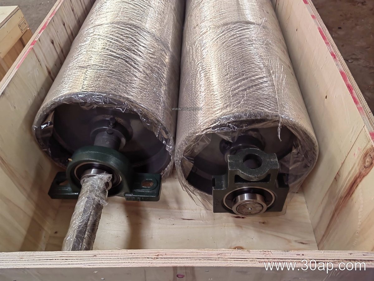
The work usually starts with a rolled or welded shell, which is machined on a horizontal boring mill or large lathe to control concentricity between the shaft and the shell surface. Shaft ends are turned to the bearing and coupling fits, keyways are cut, and end discs are welded and then finished so the drum runs without runout. For a drive pulley, the machining also has to suit the torque demand of the application, so shaft diameter is chosen from load and torque calculations rather than from belt width alone.
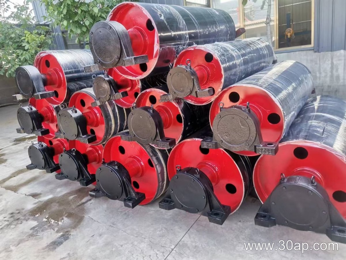
Typical Construction and Machining Steps
- Shell preparation and weld inspection before machining
- End disc and hub fitting, followed by welding and stress relief where specified
- Turning of the shell outside diameter and facing of the drum ends
- Shaft journal turning, keyway milling, and bearing seat finishing
- Dynamic balancing for high-speed or large-diameter units
- Surface preparation before lagging, painting, or assembly
Common shaft diameters for conveyor pulleys fall in the range of Ø50 to Ø200 mm, but the final value follows the calculated torque and bearing selection. Shell diameters commonly run from Ø200 to Ø1800 mm, and face widths are usually a little wider than the belt they carry, for example about 1400 mm face width for a B1200 belt or about 950 mm for a B800 belt. These are reference patterns, not fixed pairings; a B1000 conveyor may use different pulley diameters at the head, tail, and bend positions depending on tension and wrap angle.
Where Machined Pulleys Are Used
In a sand and gravel plant, the head or drive pulley at the discharge point is usually the largest and most heavily machined unit, often with lagging to improve grip. The tail pulley at the loading end keeps the belt aligned, while bend and take-up pulleys route the belt through the tensioning zone. A coal handling system in a power plant may use several machined bend pulleys to guide the belt around a tripper or a transfer tower. In each position, the machining quality of the shaft and shell matters more than the name of the position.
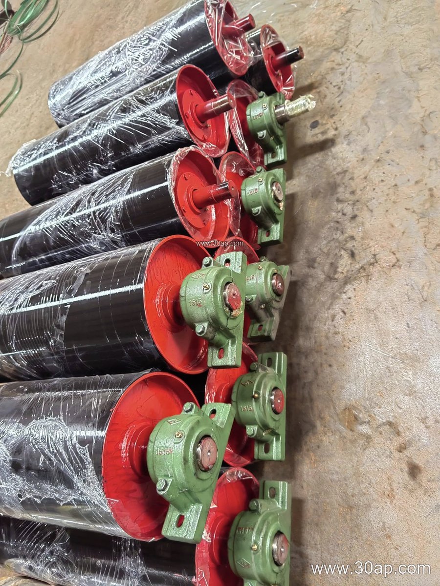
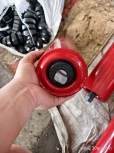
For comparison, a wing pulley is sometimes used at the tail of a coarse aggregate conveyor to shed sticky material; its construction differs from a standard machined drum, so it is not a substitute for a drive pulley. Likewise, a conveyor idler roller supports the belt along the carry side, while a conveyor pulley drives or redirects it at the ends. Both work with the conveyor belt, but their machining requirements are different.
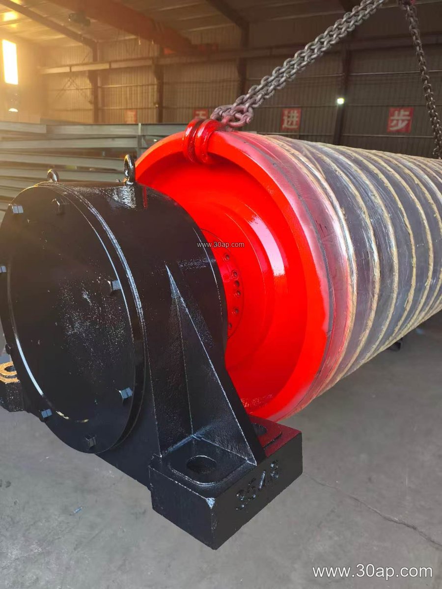
Surface Forms and Lagging After Machining
The machined shell can remain plain or receive a rubber or ceramic cover. Plain surface suits light-duty or non-driven positions. Rubber lagging is common on drive pulleys, with diamond or herringbone patterns helping to shed water and improve traction. Ceramic lagging is chosen where slip and wear are concerns. Lagging thickness commonly ranges from 8 mm to 20 mm, and the cover is applied after the shell surface has been prepared to the required finish.
| Reference item | Common range |
|---|---|
| Belt width | B400 to B2400 |
| Pulley diameter | Ø200 to Ø1800 mm |
| Shaft diameter | Ø50 to Ø200 mm |
| Lagging thickness | 8, 10, 12, 15, 20 mm |
| Surface options | plain, cold-bonded rubber, hot vulcanized rubber, diamond, herringbone, ceramic |
A combination such as B1200 × Ø1000 or B800 × Ø500 can appear in project drawings, but the correct diameter for a given belt width depends on tension, wrap angle, and the space available at the conveyor bracket.
What Buyers Should Check
When specifying conveyor pulley machining, ask for the shaft material and the calculated torque basis, the shell thickness, and the runout tolerance after finishing. Confirm whether the pulley will be supplied with bearings, bearing housings, and a conveyor bracket that matches the conveyor frame. Check that the lagging type suits the material handled, since wet coal, limestone dust, and hot clinker place different demands on the surface. Finally, request the machining report or inspection record for journal dimensions and shell concentricity so the unit can be installed without shimming or belt training problems.