What the pulley does on a sand and gravel line
In a crushing and screening circuit, the conveyor pulley is the component that turns the belt, carries the tension and keeps the load moving between jaw crushers, screens and stockpiles. The sand and gravel plant conveyor pulley must cope with abrasive aggregate, fine dust and the constant shock of material dropped from chutes. That duty is different from a clean grain line or a coal yard, so the pulley is usually built a little heavier and specified with wear protection in mind.
The work is shared by several positions on one conveyor. The drive pulley transmits torque from the gearbox to the belt. The tail pulley at the loading end turns the belt back. Bend pulleys guide the belt around the take-up system and change direction where the layout needs it. These roles are not interchangeable: a drive pulley is designed for torque and grip, while a bend pulley mainly carries tension and changes belt direction. Confusing the two is one of the most common specification mistakes.
How a sand and gravel plant conveyor pulley is built
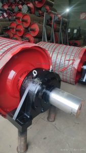
The core is a steel shell, usually machined and balanced, welded to end discs and hubs. The shaft is pressed or keyed into the hubs and sized by torque and bearing load rather than by belt width alone. Bearings sit in housings that can be bolted to the conveyor bracket, and the assembly is sealed against dust and water.
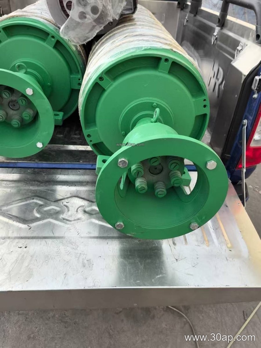
Surface treatment matters in this industry. A bare steel shell on a drive pulley can slip when the belt is wet or dusty. Common surface forms include:
- Plain or smooth shell for light duty and some bend positions
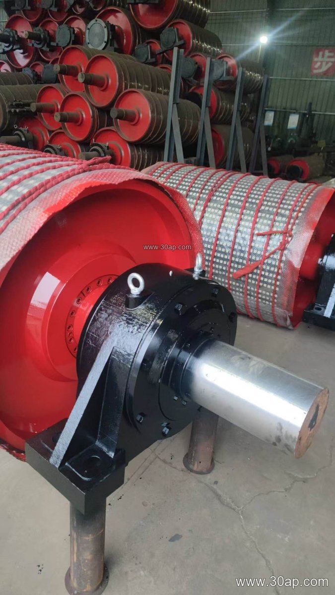
- Rubber lagging applied cold or hot vulcanized, with plain, diamond or herringbone pattern
- Ceramic lagging for high wear areas such as the head of a primary crushing conveyor
Lagging thickness is commonly 8, 10, 12, 15 or 20 mm depending on belt speed, load and abrasion. Diamond and herringbone patterns help shed water and fines, which is useful in a wash plant or after rain.
Matching pulley size to the conveyor
The shell width is normally a little wider than the belt so the belt is supported across its full width. Some typical combinations for reference are shown below; these are common examples, not fixed rules, and final sizing is set by the conveyor designer.
| Belt width | Typical shell width | Example diameter |
|---|---|---|
| B500 | about 600 mm | Ø250 to Ø400 |
| B650 | about 750 mm | Ø315 to Ø500 |
| B800 | about 950 mm | Ø400 to Ø630 |
| B1000 | about 1150 mm | Ø500 to Ø800 |
| B1200 | about 1400 mm | Ø630 to Ø1000 |
| B1400 | about 1600 mm | Ø800 to Ø1250 |
| B1600 | about 1800 mm | Ø1000 to Ø1400 |
Diameter affects belt wrap and bending stress. A larger pulley reduces the reverse bending fatigue on the belt and is often preferred at the head of a high tension conveyor. A smaller diameter saves space at a bend or take-up position. Shaft diameters are commonly in the range Ø50 to Ø200 mm, but the correct value comes from torque, bearing life and load calculations, not from the belt width alone.
Where it is used and what to check before ordering
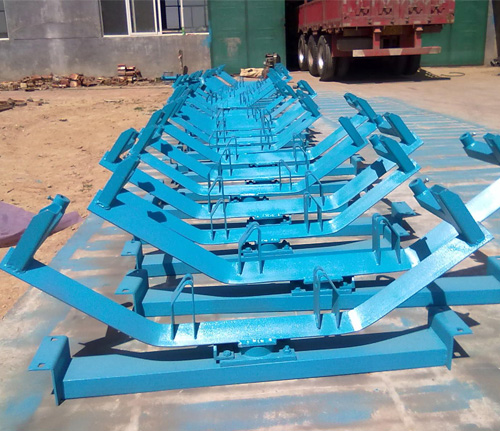
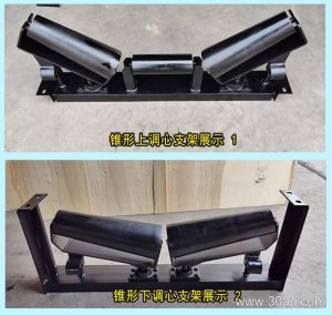
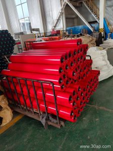
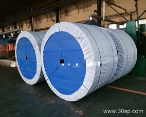
These pulleys appear across aggregate and mineral processing: a quarry primary conveyor, a limestone crushing and screening plant, a concrete batching plant feed line, a tunnel muck removal conveyor, or a stockyard transfer in a cement works. In each case the belt, idler roller set, conveyor bracket and pulley must be treated as one system.
Buyers should confirm the belt width, the pulley position (drive, tail, bend or take-up), the required diameter, lagging type and thickness, shaft and bearing arrangement, and the mounting bracket dimensions. Ask for the balancing class and the sealing arrangement if the plant is dusty or washed down regularly. Also check that the pulley face width suits the belt and that the lagging can be replaced without removing the whole shaft assembly. A well matched sand and gravel plant conveyor pulley, together with the conveyor belt and idler rollers in good condition, keeps a crushing circuit running with fewer stoppages.