What the Trough Idler Bracket Set Does
A trough idler bracket set is the mounting frame that positions three idler rollers in a trough shape under the conveyor belt. It supports the belt on the carrying side, keeps the belt edges raised, and helps contain bulk material during transport. In a quarry, coal preparation plant, or cement plant, these bracket sets are part of the everyday structure that keeps the belt line running true. The set usually includes the main bracket frame, mounting plates or angles, and the connection points for the idler roller shafts.
Construction and Common Materials
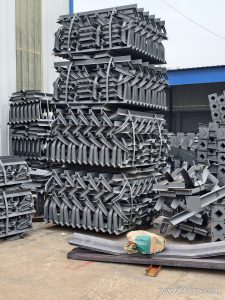
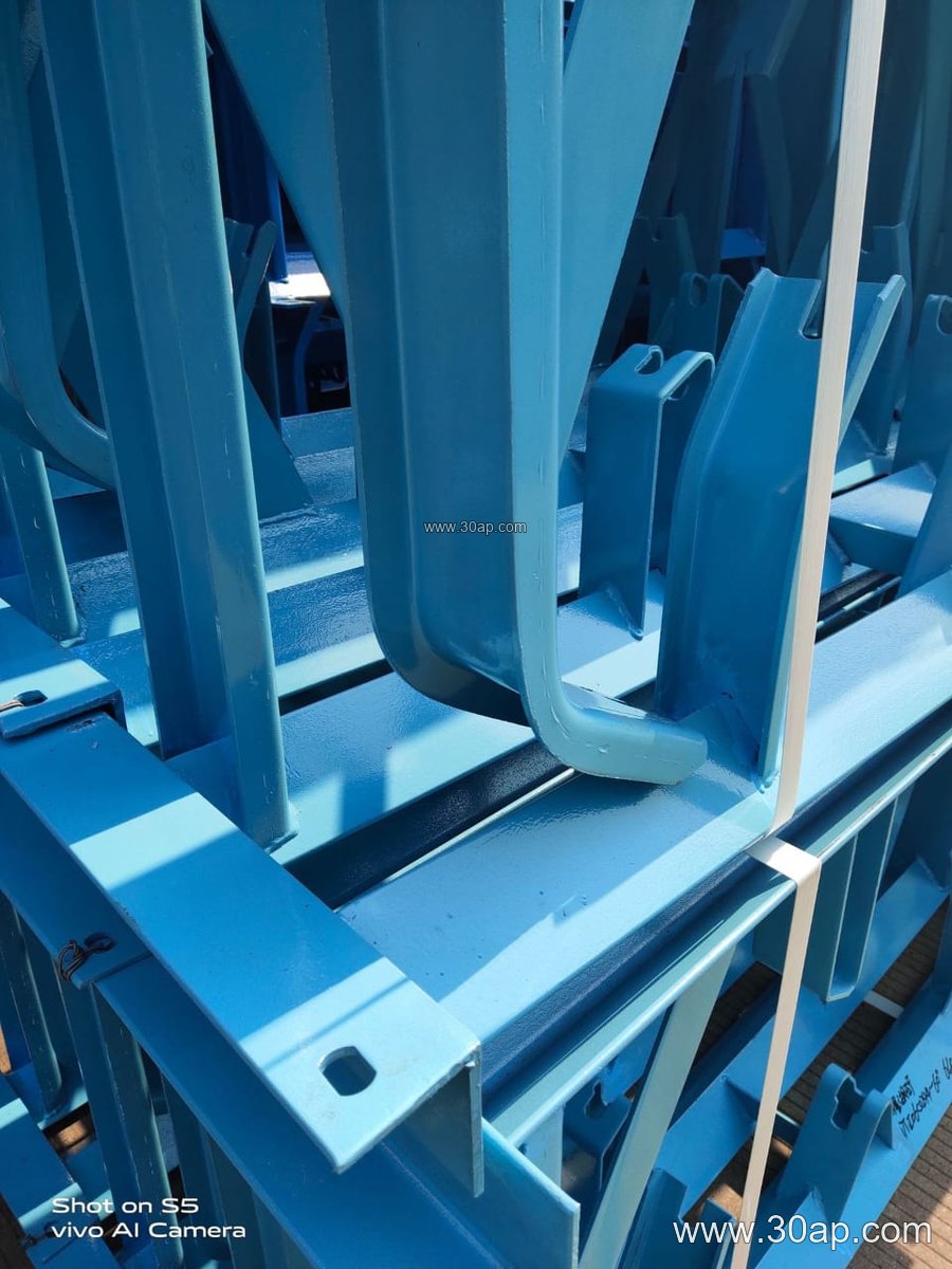
Most trough idler bracket sets are fabricated from angle steel, channel steel, or bent steel plate. The frame is designed to hold the center roller flat and the two side rollers at a chosen trough angle. Common angles are 20, 30, 35, and 45 degrees. Adjustable versions allow the same bracket set to be set at different trough angles within a range. Fixed versions are welded or bolted to a specific angle. The bracket set may also include slotted holes or shims for alignment during installation.
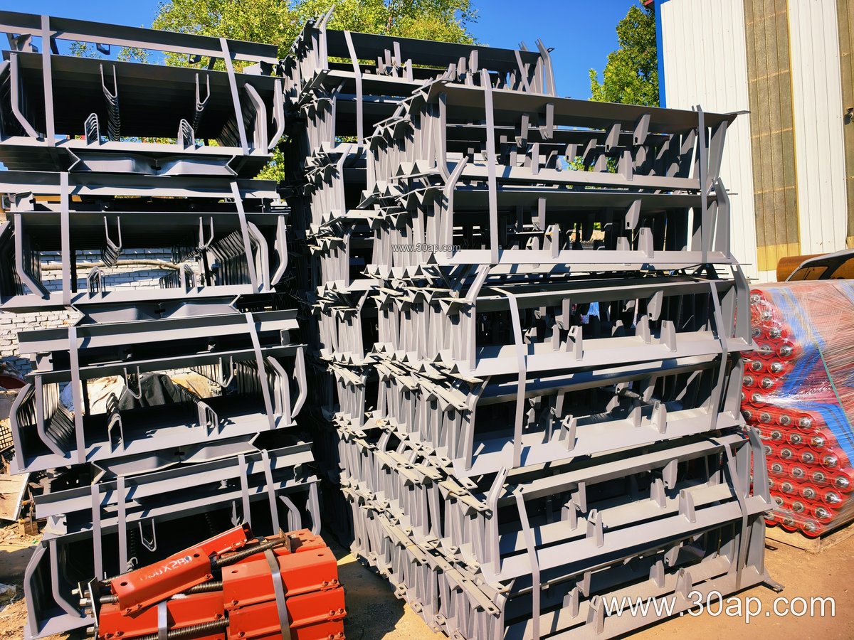
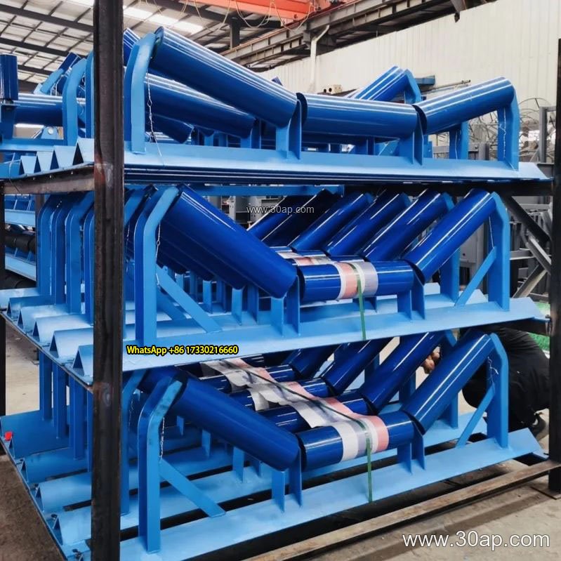
- Main frame: angle or channel steel, sometimes bent plate
- Roller seats: formed to match the idler shaft ends
- Mounting holes: spaced according to belt width and bracket design
- Finish: painted or galvanized depending on the environment
Where It Fits on the Conveyor
The bracket set is installed on the carrying side of the conveyor frame, between the conveyor pulleys. It is not a substitute for a drive pulley, tail pulley, or bend pulley; those components handle power transmission and belt direction. The trough idler bracket set works together with the conveyor belt and idler rollers to form the trough profile. In a sand and gravel line or a power plant coal handling system, several bracket sets are spaced along the conveyor to support the loaded belt. A common arrangement uses a B800 belt with 35-degree trough angle and Ø108 idler rollers, but the exact match depends on the conveyor design.
Typical Sizes and Configuration Examples
Bracket sets are usually selected to match the belt width and the idler roller diameter. The table below shows common reference combinations; these are examples, not fixed rules for every conveyor.
| Belt Width | Trough Angle | Idler Roller Diameter | Typical Use |
|---|---|---|---|
| B500 | 20-30 degrees | Ø89 | Small conveying lines, light material |
| B650 | 30 degrees | Ø89 or Ø108 | Sand and gravel, small crushing plants |
| B800 | 35 degrees | Ø108 | General bulk handling, cement plants |
| B1000 | 35-45 degrees | Ø133 | Coal preparation, power plant coal lines |
| B1200 | 45 degrees | Ø133 or Ø159 | Heavy-duty quarry and mining conveyors |
| B1400 | 35-45 degrees | Ø159 | Iron ore, large tonnage conveying |
| B1600 | 35-45 degrees | Ø159 or Ø194 | High-capacity bulk systems |
Mounting hole spacing and crossbeam length vary with belt width, trough angle, and bracket design. They should be confirmed with the conveyor frame drawing before ordering.
Selection and Maintenance Notes
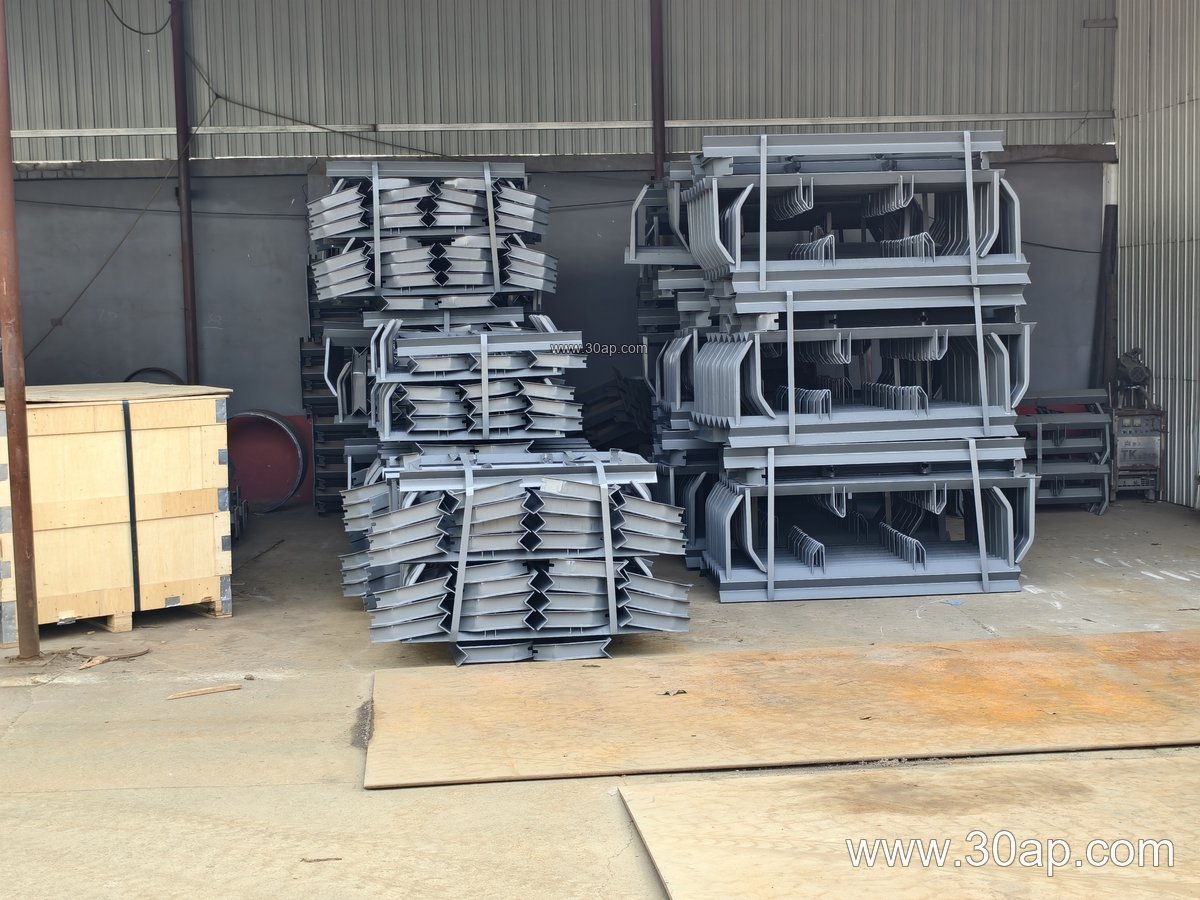
When choosing a trough idler bracket set, match the bracket to the idler roller shaft size and the conveyor frame. Check whether a fixed or adjustable bracket is needed. Adjustable brackets can help fine-tune belt tracking and trough angle during commissioning. In dusty locations such as a limestone mine or a fertilizer plant, inspect the bracket set for material buildup and bolt tightness. Replace bent or heavily worn brackets to keep the idler rollers aligned and the conveyor belt running smoothly.
For comparison, a return bracket set supports the belt on the return side and may use a flat or V-shaped arrangement. It is a different component and should not be used in place of a trough idler bracket set on the carrying side.