What an Anti-Impact Idler Does
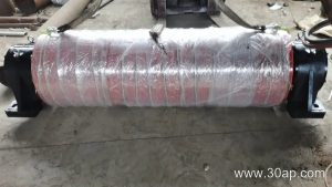
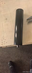
An anti-impact idler is a heavy-duty carrying roller placed where the conveyor belt receives its load. Instead of a rigid steel shell, it uses rubber rings or a rubber-covered surface to absorb the energy of falling rock, ore, or aggregate. This cushioning action protects the belt from cuts and punctures and reduces stress on the idler frame and bearings. In a quarry, a coal preparation plant, or a cement plant, the loading zone is the harshest part of the conveyor. The anti-impact idler is built specifically for that spot.
Construction and Common Forms
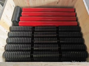
The core of an anti-impact idler is a steel tube fitted with a series of thick rubber discs, often called rubber ring buffer idlers. The rubber rings are spaced along the roller length and can be replaced individually. Some designs use a continuous rubber sleeve instead of separate rings. Bearings are sealed to keep out dust and water, and the shaft is usually made from cold-drawn steel. Common bearing numbers include 6204, 6205, 6305, 6306, 6308, and 6310, but the bearing is selected by the idler manufacturer to match the load and speed, not by belt width alone.
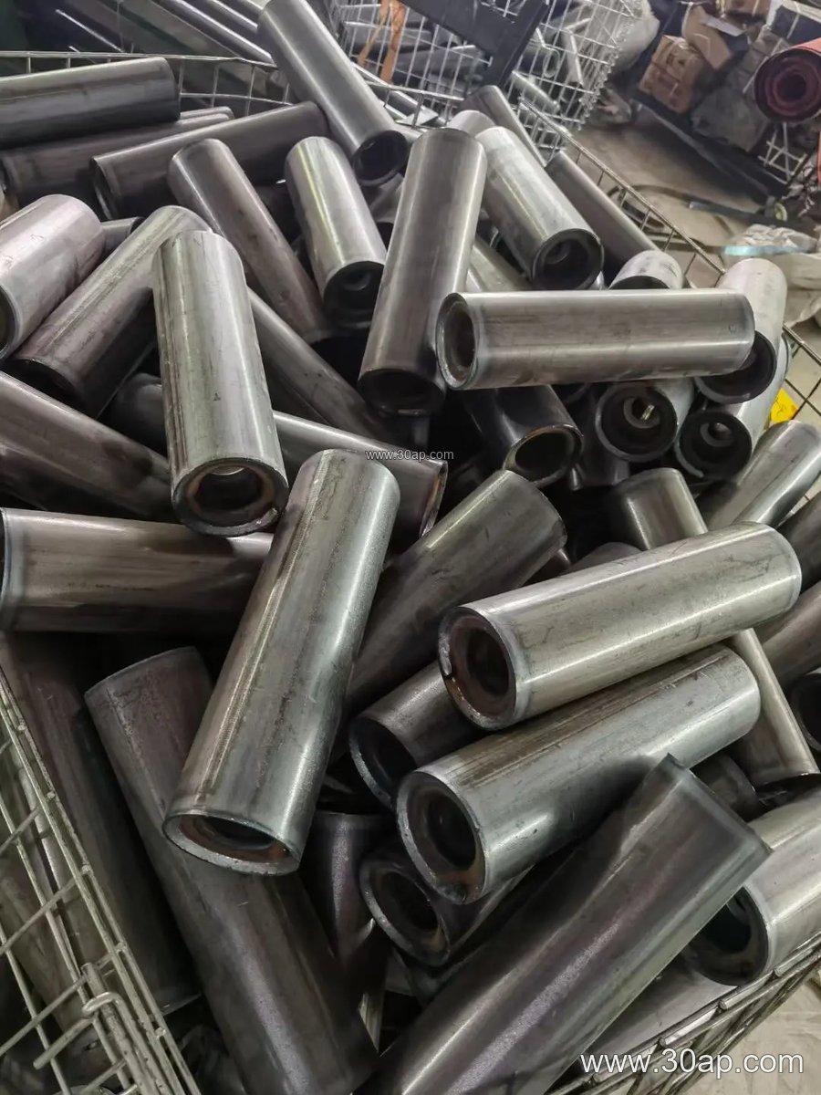
Roller diameters for buffer idlers typically follow the standard idler range: Ø89, Ø108, Ø127, Ø133, Ø159, and Ø178 mm are common. The roller length depends on belt width, trough angle, and whether the idler is a single roller or part of a three-roll trough set. For example, a three-roll trough set on a B800 belt often uses a centre roller around 315 mm long, while a B1200 set may use a centre roller around 465 mm. These are common examples, not fixed rules. The side rollers can differ from the centre roller.
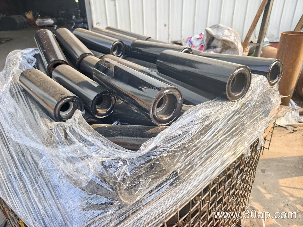
Where It Fits on the Conveyor
Anti-impact idlers are installed at the feed point, directly under the chute or transfer tower. They are usually arranged as a close-spaced group of three or five idlers to spread the load. In a sand and gravel line, the primary crusher discharge is a typical location. In a power plant coal handling system, the belt loading station after the coal feeder uses them. They are not a replacement for standard carrying idlers along the full conveyor; they only appear in the impact zone. Return idlers, training idlers, and transition idlers serve different purposes and are not interchangeable with the buffer type.
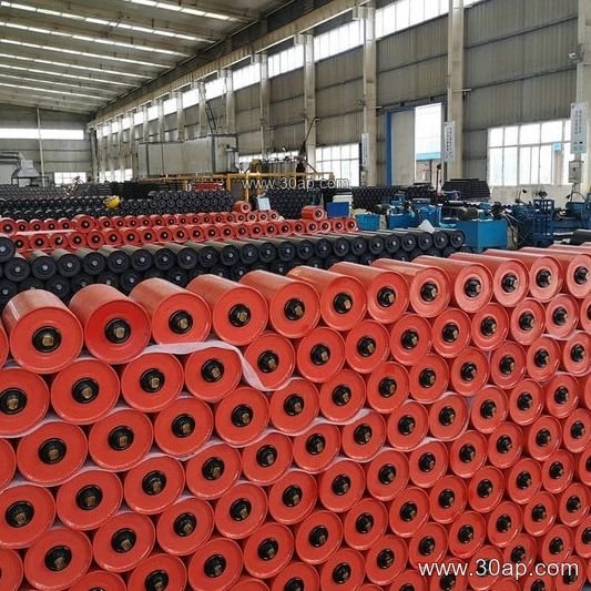
For comparison, a standard trough idler with a steel shell is fine on the carrying run where material is already settled. A return idler supports the empty belt. A transition idler guides the belt from flat to troughed. Only the anti-impact idler is designed to take the repeated hammering of large lumps at the loading point.
Selection Details a Buyer Should Check
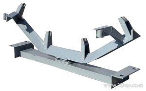
Before ordering, confirm the belt width, the trough angle, and the mounting dimensions of the existing idler frame. The conveyor bracket spacing and shaft end configuration must match. Ask for the rubber hardness and ring thickness if the material includes sharp, heavy rock. Check the bearing seal type for dusty or wet conditions. A buyer should also consider the drop height and lump size, because a very high drop may need a longer impact bed or a different cushioning arrangement. Do not assume that one roller diameter fits every belt width; the idler supplier will match the shaft and bearing to the actual load.
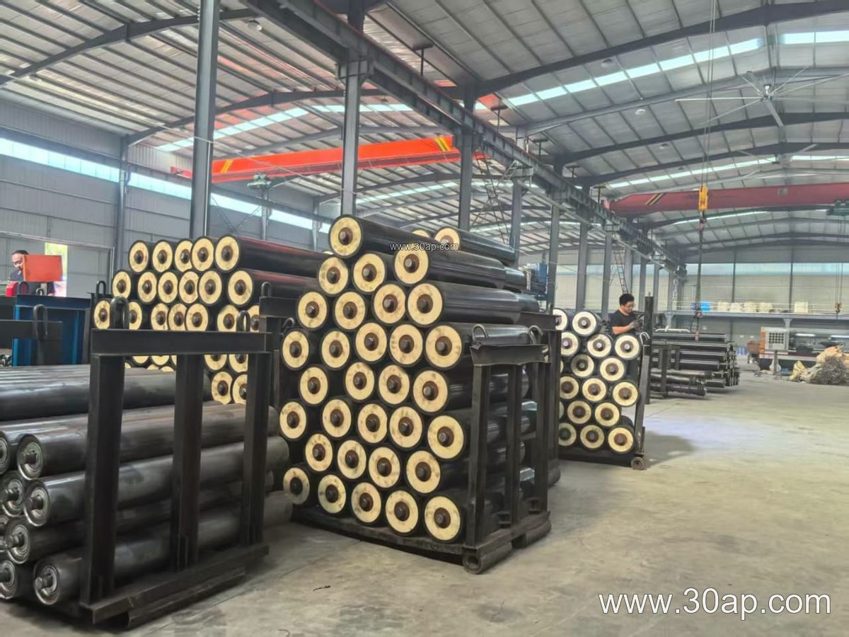
Common belt widths for buffer idler sets include B500, B650, B800, B1000, B1200, B1400, B1600, and B1800. Trough angles are usually 20, 30, 35, or 45 degrees. The table below shows typical reference values, but final dimensions are determined by design.
| Belt width | Typical centre roller length (three-roll trough) | Common idler diameter range |
|---|---|---|
| B500 | 200 mm | Ø63 to Ø108 mm |
| B650 | 250 mm | Ø76 to Ø127 mm |
| B800 | 315 mm | Ø89 to Ø133 mm |
| B1000 | 380 mm | Ø108 to Ø159 mm |
| B1200 | 465 mm | Ø108 to Ø178 mm |
| B1400 | 530 mm | Ø127 to Ø178 mm |
| B1600 | 600 mm | Ø133 to Ø194 mm |
| B1800 | 670 mm | Ø159 to Ø219 mm |
These values are reference data for common three-roll trough sets. Side rollers and single-roller impact idlers may have different lengths. The shaft diameter is not fixed by belt width; it depends on the idler series and load rating. Always request a dimensional drawing before installation.
Maintenance Notes
Inspect the rubber rings for wear, cuts, or missing pieces. Replace worn rings before the steel core is exposed. Check that the idler rotates freely and that the seal has not been damaged by fines. In a dusty quarry or a wet coal plant, keep the impact zone clear of build-up. A well-chosen anti-impact idler reduces belt damage and downtime at the loading point, but it still needs routine attention like any other conveyor component.