What a Belt Guide Roller Does on a Conveyor
A belt guide roller is a small but critical component that keeps a conveyor belt centered and running smoothly along its intended path. Unlike main load-bearing idlers, which support the weight of the material, this roller is primarily a tracking device. It is often installed at points where the belt is most likely to wander—near the head or tail, before or after a curve, or in sections with uneven loading. By applying gentle lateral force, the guide roller corrects minor misalignment before it becomes a major problem such as edge damage, spillage, or excessive wear on the conveyor pulley.
In many conveyor systems, a belt guide roller is also known as a training roller or self-aligning roller. These terms refer to the same tracking function, though the exact design may vary. It is not a drive pulley, tail pulley, or bend pulley, and it should never be used to replace those components. Those pulleys transmit power or change the belt direction; the guide roller only influences belt position.
How a Belt Guide Roller Is Built
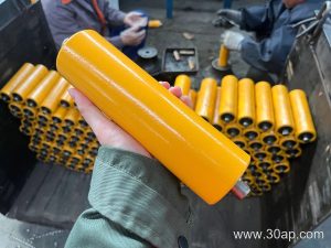
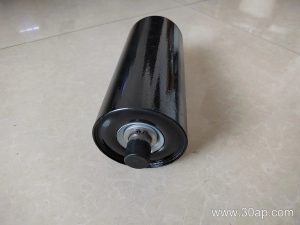
Construction of a belt guide roller typically follows the same basic pattern as other idler rollers, but with features that enhance steering. The body is usually a steel tube, often with a machined or painted surface. In dusty or corrosive environments, nylon or rubber-covered rollers may be chosen. Ceramic coatings are also available for extremely abrasive conditions, though they are less common on guide rollers than on load idlers.
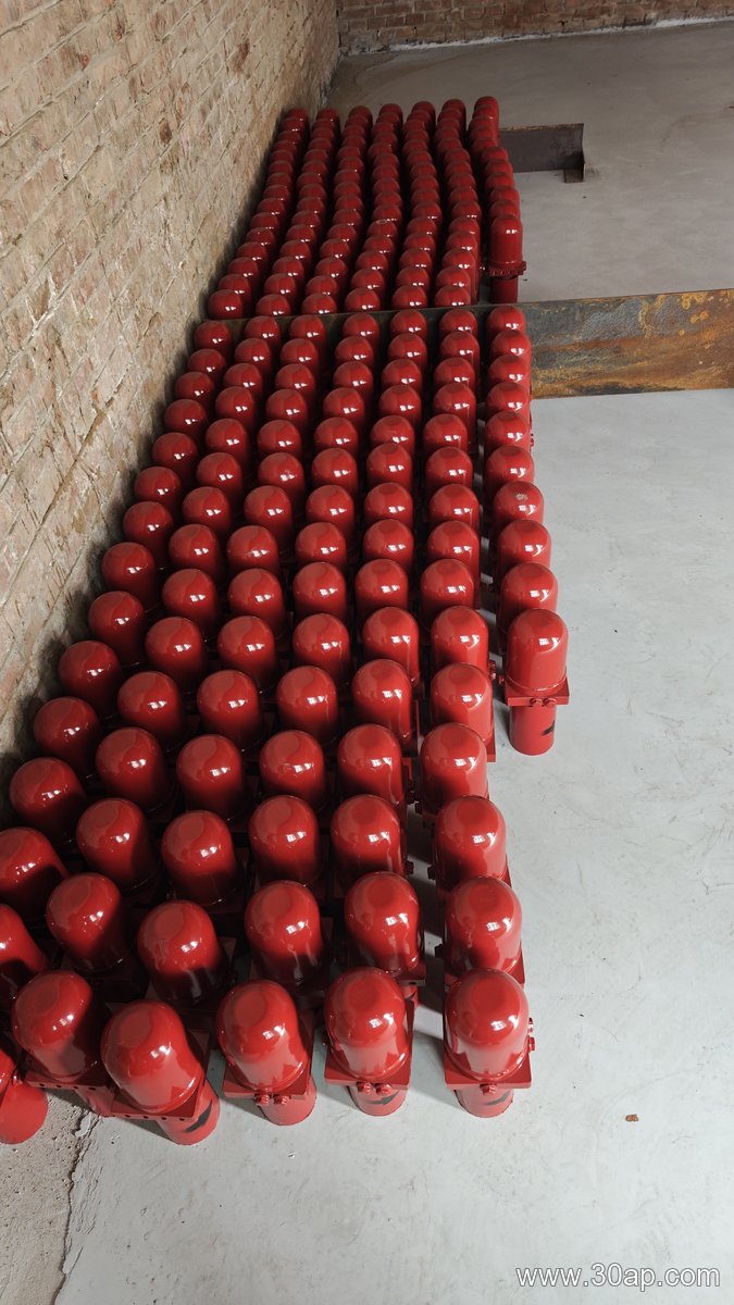
Inside, the roller runs on bearings—common sizes include 6204, 6205, 6305, 6306, 6308, and 6310. The bearing is protected by a seal, which may be a simple labyrinth, a contact seal, or a combination. Proper sealing is vital because a seized guide roller will not steer the belt and can cause flat spots or belt damage. The shaft is usually fixed to a conveyor bracket or frame, while the roller shell rotates freely.
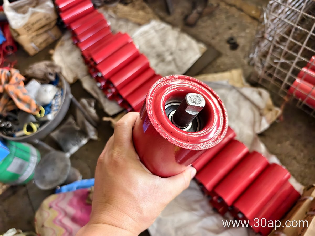
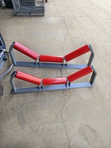
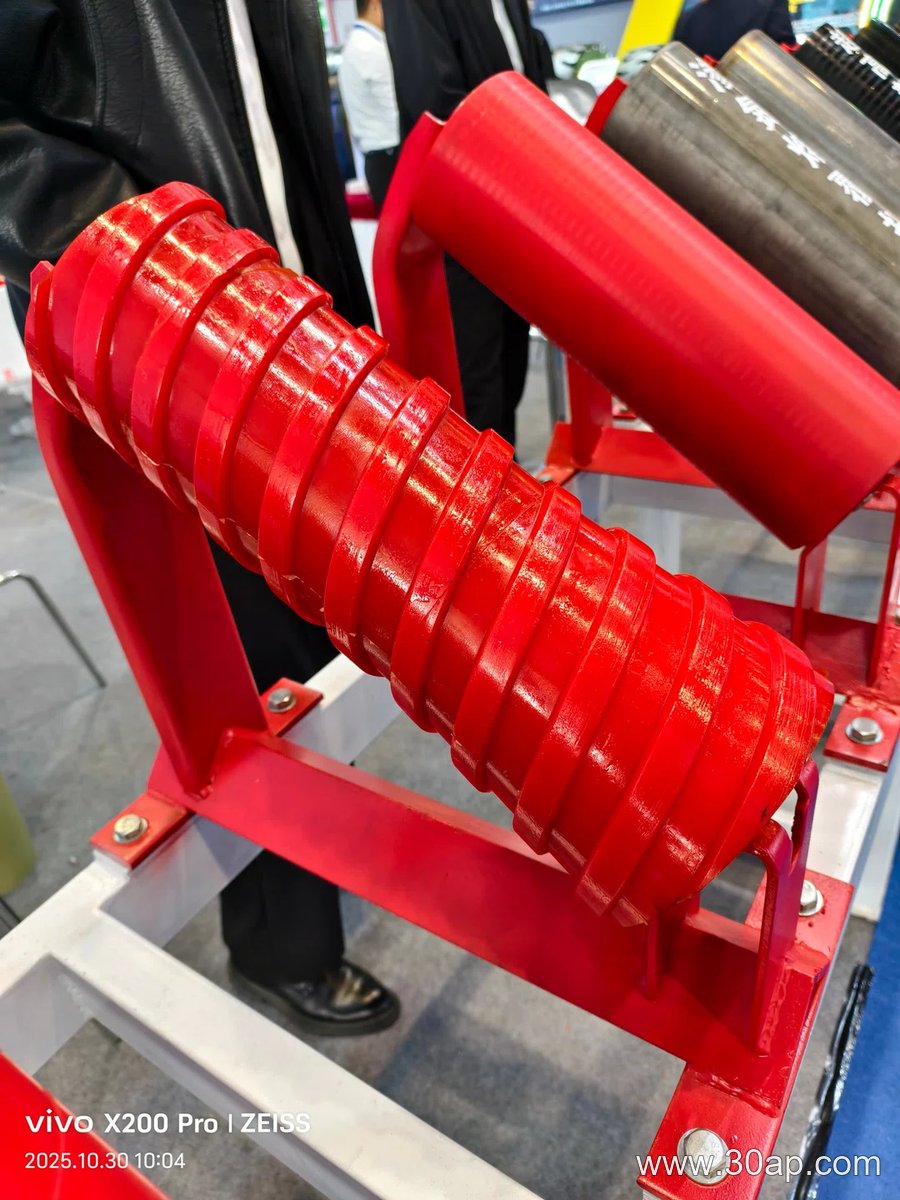
Some belt guide rollers are designed as a single cylindrical unit. Others are part of a larger assembly, such as a two-roller or three-roller set with a V-shaped or troughing profile. The guide function may be built into a tapered roller, a spiral roller, or a friction-type self-aligning roller. Each subtype has its own mounting and adjustment method, but all share the goal of maintaining belt alignment.
Where Belt Guide Rollers Are Used
These rollers appear in almost every industry that relies on a conveyor belt. In a quarry or limestone mine, a belt guide roller helps keep the belt on track despite uneven loading from a crusher or screen. In a coal washing plant, the roller may be positioned before the head pulley to prevent the belt from rubbing against the chute. In a port terminal handling bulk cargo, guide rollers are often found on the return strand to correct drift caused by wind or off-center feeding.
They are also used in sand and gravel lines, cement plants, power station coal conveying, and tunnel muck removal. The choice of location depends on the belt path and the consequences of misalignment. A single guide roller placed just ahead of a critical transfer point can often eliminate the need for more complex training idlers.
Matching the Roller to Belt Width and Trough Angle
Belt width and trough angle influence the size and mounting of a belt guide roller. Common belt widths include B400, B500, B650, B800, B1000, B1200, B1400, B1600, B1800, B2000, B2200, and B2400. For a three-roll troughing set, the side roller length typically varies with belt width—for example, a B500 belt might use a 200 mm side roller, while a B1200 belt often uses a 465 mm roller. These are common examples, not fixed rules. The middle roller can differ from the side rollers, and the guide roller itself may be shorter or longer than the load-carrying rollers.
Trough angles of 20, 30, 35, and 45 degrees are standard. A belt guide roller may be mounted at the same angle as the troughing idlers, or it may be set at a slight forward tilt—often about 1.5 to 2 degrees—to encourage self-centering. This forward tilt is a design detail, not a universal requirement. The roller diameter can range from Ø63 to Ø219, but the correct size depends on belt speed, load, and the space available in the conveyor bracket. A larger diameter roller turns more slowly and may last longer in abrasive service, but it also requires more clearance.
Selection and Maintenance Pointers for Buyers
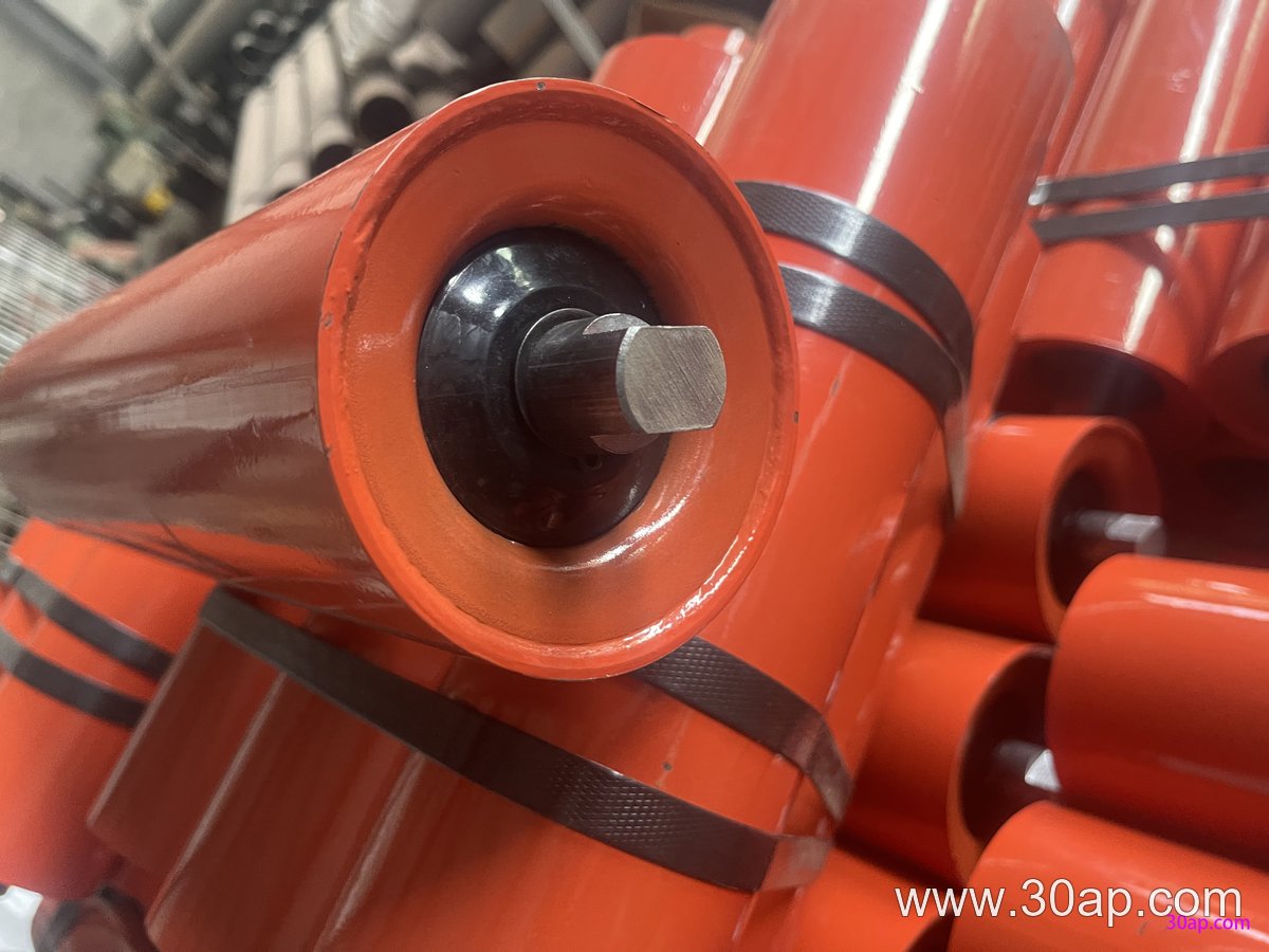
When specifying a belt guide roller, start with the belt width and the available mounting space. Then consider the environment: wet, dusty, or corrosive conditions call for better seals and possibly a different roller surface. If the belt carries sticky material, a rubber-covered or spiral roller may shed buildup better than a plain steel roller. For extreme impact, a buffer roller or rubber-ring buffer roller might be used nearby, but those are different products and should not be confused with a guide roller.
Check that the roller can be adjusted after installation. Many guide rollers are mounted on brackets that allow lateral shimming or angular change. This adjustability is essential because belt tracking often changes with load, belt tension, and weather. A roller that cannot be adjusted may become useless once the belt stretches or the structure settles.
Inspect guide rollers during routine maintenance. Look for smooth rotation, seal leakage, and buildup on the roller surface. A worn or seized guide roller can cause more harm than no roller at all, because it may drag on the belt edge or create a pivot point that worsens misalignment. Replacing a guide roller is usually simple, but the replacement must match the shaft diameter, bearing size, and mounting pattern of the original. Do not assume that a roller from one belt width will fit another without checking dimensions.
Finally, remember that a belt guide roller is one part of a tracking system. It works together with the conveyor pulley alignment, the idler roller frames, and the belt splice. If misalignment persists after installing or adjusting guide rollers, inspect the entire conveyor for structural issues, off-center loading, or a damaged conveyor bracket. Correcting the root cause is always better than adding more rollers.