Calculating Conveyor Belt Length for a Cement Plant Transfer
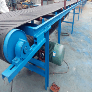
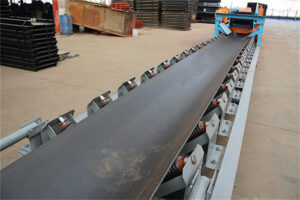
In a hypothetical cement plant, a conveyor belt moves crushed limestone from a hopper to a storage pile. The layout fixes the pulley center distance at 40 meters. To order a replacement belt, you need to calculate its length. This article explains the method and assumptions.
Assumptions and Inputs
- Center distance (C): 40 m
- Drive pulley diameter (D): 1.0 m
- Tail pulley diameter (d): 0.8 m
- Belt wrap angle: 180° on both pulleys (typical for simple two-pulley system)
- Take-up allowance: 1.5% of calculated length for splicing and tensioning
Step-by-Step Calculation
For a two-pulley system with 180° wrap, the approximate belt length (L) is:
L = 2C + π(D + d)/2
Plugging in values:
L = 2 × 40 + π × (1.0 + 0.8)/2
L = 80 + π × 0.9 ≈ 80 + 2.827 = 82.827 m
Add 1.5% take-up allowance: 82.827 × 1.015 ≈ 84.07 m. Round up to 84.1 m.
Why This Matters for Conveyor Belt Selection
An incorrect length leads to either insufficient belt for splicing or excess slack that misaligns the belt. In a cement plant, dust and heat can accelerate wear, so accurate length calculation supports reliable operation. Always verify pulley diameters and center distance on site before ordering.
Additional Considerations
If the conveyor has a gravity take-up, the required belt length may need extra allowance. For inclined conveyors, the center distance is measured along the incline. This example is hypothetical; actual projects require detailed engineering.
Why an Idler Roller Fails in a Dusty Quarry
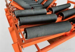
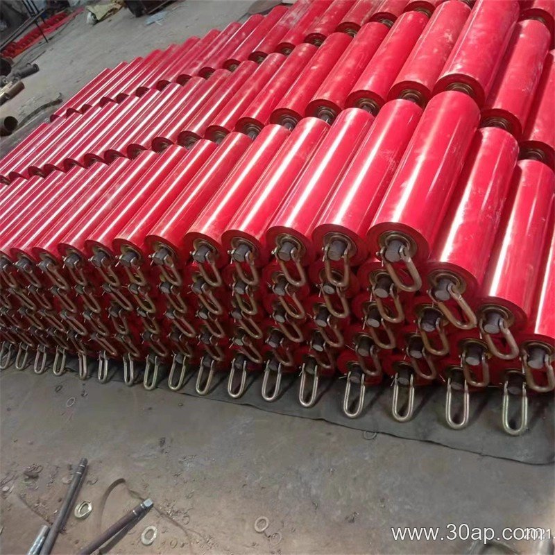
What makes an idler roller seize or grow noisy in a quarry full of airborne grit? The direct answer is that abrasive dust has entered a sealing or bearing zone, or that the roller has been overloaded or misaligned. Before replacing parts, check three things: whether the shell rotates freely by hand, whether the bearing housing shows play or heat marks, and whether the roller sits square to the belt line.
Symptoms That Point to the Idler Roller
A failing idler roller rarely fails silently. Common symptoms include a squealing or grinding note that changes with belt speed, a hot bearing housing after short running, belt drift toward one side, and visible belt cover wear directly above one roller position. In a quarry, fine rock dust can also build a crust on the shell, causing an out-of-balance condition that feels like vibration rather than noise.
Plausible Causes Behind the Same Symptom
Contaminated Bearing Lubricant
Dust that passes a worn seal mixes with grease and forms an abrasive paste. The bearing then runs rough and hot. This cause is likely when several idler rollers in the same dusty zone fail within a short period.
Seal Damage From Impact or Spillage
Fallen rock can strike the roller end and deform the seal lip. The idler roller may still turn, but grit enters with every rotation. Inspect the shell end for dents or fresh gouges before blaming the bearing.
Misalignment or Uneven Loading
A roller set that is not square to the belt imposes axial thrust on the bearings. The symptom is often belt wander plus edge wear, not just noise. Check the frame and mounting slots first, because a new idler roller will fail the same way if the structure remains skewed.
Shell Wear or Material Buildup
In a quarry, abrasive material can wear through a thin shell wall or stick to a damp shell. Either condition changes the roller diameter and balance. A hypothetical example: a 10 mm wall reduced to 4 mm locally may flex under load, loosening the end disc.
How to Separate the Causes
- Isolate the noisy idler roller and rotate it by hand; roughness suggests bearing damage, while wobble suggests a bent shaft or loose end disc.
- Compare adjacent rollers; one failed unit points to impact, several point to dust ingress or alignment.
- Check temperature after a short run; a hot housing supports lubrication or overload problems.
- Review belt tracking; drift supports alignment or roller-diameter issues.
Fault analysis works best when symptoms are matched to evidence, not guessed. In dusty service, sealed idler roller designs and regular inspection usually separate a short service life from a long one.
Conveyor Pulley Diameter: A Trade-Off Between Belt Stress and Torque
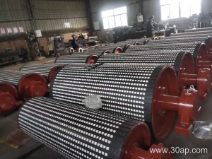
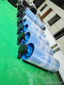
When specifying a conveyor pulley for a cement plant, engineers often default to a larger diameter to reduce belt bending stress. But that choice increases torque and cost. The decision hinges on a technical term: rated torque. Rated torque is the maximum continuous torque a conveyor pulley can transmit without exceeding its design stress limits. It depends on shaft diameter, shell thickness, and hub design—not just pulley diameter. A larger pulley may lower belt stress but raise the torque required at the drive, potentially demanding a larger shaft and bearings. In a cement plant, where space and maintenance access are tight, this trade-off matters.
How Rated Torque Affects Selection
Rated torque is not a single number on a nameplate; it is a calculated limit based on the pulley’s weakest component. For a given belt tension and wrap angle, the required torque is fixed. If the pulley’s rated torque is too low, the shaft may fatigue or the lagging may slip. Conversely, oversizing the pulley to gain torque margin adds weight and inertia, which can strain the take-up system. In a hypothetical cement plant, a 400mm diameter conveyor pulley might have a rated torque of 12 kN·m, while a 500mm pulley of the same construction could handle 18 kN·m—but at 20% more cost and 30% more weight. The engineer must check whether the smaller pulley’s rated torque exceeds the application’s demand with a safety factor.
Practical Decision Points
- Belt tension and wrap angle: Higher tension or a smaller wrap angle increases required torque, favoring a larger pulley or a higher-rated design.
- Shaft deflection: A larger diameter pulley reduces belt bending stress but may increase shaft span, requiring a stiffer shaft to maintain rated torque.
- Lagging type: High wear-resistant lagged pulley surfaces improve grip, allowing a smaller diameter to transmit the same torque without slip.
In cement plant conveyors, dust and heat add another layer. A conveyor take-up pulley must accommodate belt stretch without losing alignment, so its rated torque must account for dynamic loads during startup. The key is to match rated torque to the actual duty, not to chase a larger diameter for its own sake.
Can a Standard Conveyor Bracket Survive a Wet Outdoor Conveyor?
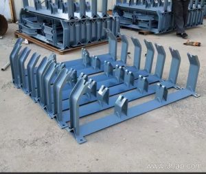
A common misconception is that any galvanized conveyor bracket will last outdoors. In reality, a wet outdoor conveyor exposes the bracket to constant moisture, temperature swings, and abrasive slurry. The bracket must not only support idler rolls but also drain water and resist corrosion at every edge. This article walks through a hypothetical selection for a wet outdoor conveyor with one meaningful dimensional constraint: the mounting bolt spacing on the existing frame is fixed at 200 mm. All project values are illustrative.
Define the Dimensional Constraint First
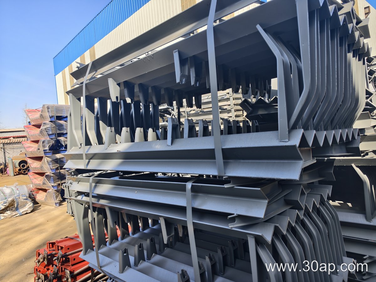
In this hypothetical project, the conveyor bracket must fit a 200 mm bolt spacing. That constraint eliminates many off-the-shelf brackets. It forces a choice between a custom bracket or an adjustable one with slotted holes. For a wet environment, slots can trap water and accelerate corrosion, so a fixed-hole design with a small drainage gap is preferable. The bracket also needs a minimum clearance of 50 mm below the idler roll to let water and fines pass.
Material and Shape Trade-offs for Wet Service
Hot-dip galvanized steel offers a thick zinc coating that protects cut edges, but it can chip during impact. Stainless steel 304 resists corrosion better but costs more and may gall at bolted joints. For this hypothetical project, a hot-dip galvanized bracket with a 6 mm thickness and a 5° slope on the top face is chosen. The slope sheds water, and the 200 mm bolt spacing is matched exactly. No adjustment slots are used.
Load Check and Practical Notes
Assume the bracket carries one idler roll with a 500 N radial load. A simple static check shows the bracket’s bending stress is well below yield for 6 mm galvanized steel. The critical detail is the drainage gap: without it, water pools at the base and corrosion begins. For any wet outdoor conveyor, verify bolt spacing, provide drainage, and avoid pockets. This example shows how one dimensional constraint drives the entire conveyor bracket selection.