What Pulley Machining Involves
Pulley machining is the process of turning, welding, and finishing a conveyor pulley so it runs true on the shaft and handles the belt load without vibration. In a quarry or a coal handling plant, a poorly machined drum shows up fast as belt tracking problems, edge wear, and bearing noise. The work covers the shell, the end discs, the shaft, and the hub, and it usually ends with a surface treatment such as plain finish, rubber lagging, or ceramic lagging. This article uses “conveyor pulley” as the natural product name; the same item is also called a conveyor drum in many workshops.
How a Conveyor Pulley Is Built
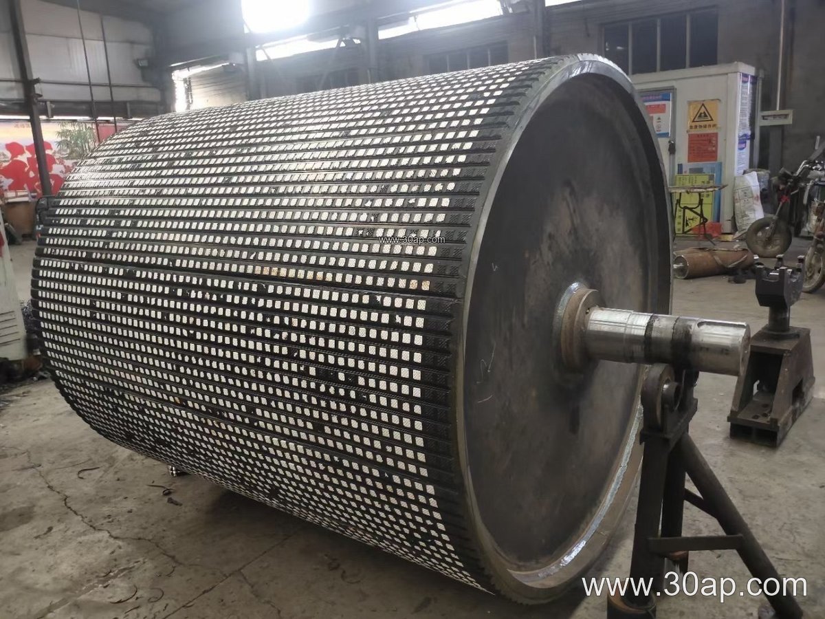
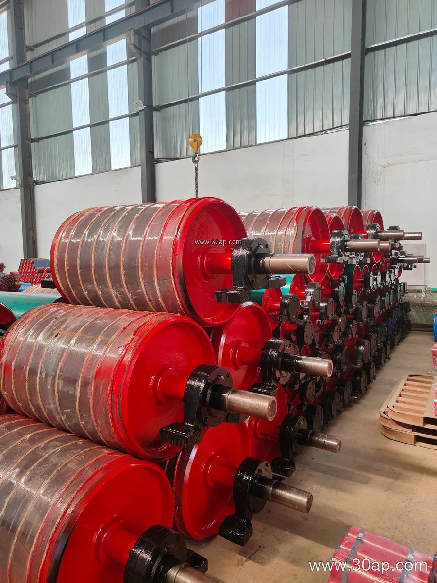
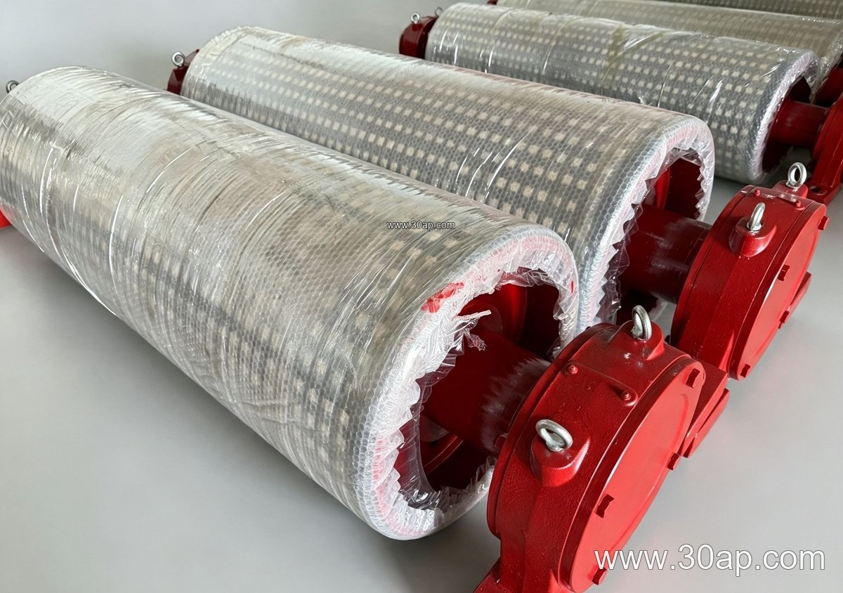
A typical drum starts with a rolled steel shell. End discs are welded in, then the shaft is fitted and the whole assembly is machined so the outside diameter and the shaft seats share a common centerline. For heavier duty, the shell may be stress-relieved before final machining. The finished surface can be left plain or covered with cast rubber, cold-bonded rubber, hot-vulcanized rubber, diamond lagging, herringbone lagging, or ceramic lagging. Lagging thickness is commonly 8, 10, 12, 15, or 20 mm, chosen for grip and wear rather than for looks.
Where It Fits in the Conveyor
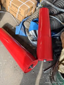
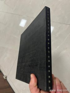
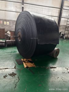
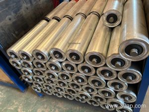
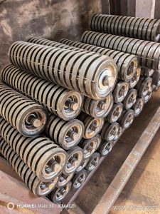
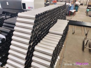
Position matters. A drive pulley transmits torque and needs a solid shaft and good lagging grip. A tail pulley at the loading end may be plain or lagged, and a bend pulley simply changes belt direction. These are not interchangeable names, and a buyer should state the position clearly. In a limestone mine, the head pulley often works with an abrasion resistant conveyor belt, while a cement plant may pair a bend pulley with a heat resistant conveyor belt near the clinker cooler. Underground coal mining conveyors usually call for flame retardant conveyor belt and well-sealed pulley assemblies. The pulley does not work alone: conveyor idler rollers support the belt on the carry side, and conveyor brackets hold the whole frame in line.
Common Size Ranges and Surface Options
Dimensions are set by belt width, belt tension, and shaft load. The table below gives common reference ranges, not fixed rules. A wider belt does not automatically mean a larger diameter, and shaft diameter should be calculated from torque and load, not copied from belt width.
| Parameter | Common reference values |
|---|---|
| Belt width B | B400, B500, B650, B800, B1000, B1200, B1400, B1600, B1800, B2000 |
| Pulley diameter | Ø200, Ø250, Ø315, Ø400, Ø500, Ø630, Ø800, Ø1000, Ø1250 |
| Face width (examples) | B400 ≈ 500 mm; B800 ≈ 950 mm; B1200 ≈ 1400 mm; B1600 ≈ 1800 mm |
| Shaft diameter | Ø50, Ø60, Ø70, Ø80, Ø90, Ø100, Ø120, Ø140, Ø160 |
| Lagging thickness | 8, 10, 12, 15, 20 mm |
| Surface forms | Plain, cast rubber, cold-bonded rubber, hot-vulcanized rubber, diamond, herringbone, ceramic |
Useful combinations such as B800 × Ø500 or B1200 × Ø1000 appear in design drawings, but they are examples of matching, not a catalogue rule. Face width is normally a little wider than the belt to allow for misalignment.
What a Buyer Should Check
- State the pulley position: drive, tail, bend, take-up, or snub. Each has different loads.
- Give belt width, belt type, and belt tension. An EP conveyor belt and a steel cord conveyor belt load the shaft differently.
- Specify lagging only if grip or wear protection is needed; plain finish is fine for many bend positions.
- Ask for the shaft diameter calculation basis, not just a number.
- Confirm the interface with conveyor idler rollers and conveyor brackets so the frame fits on site.
Good machining shows in concentricity, a smooth weld profile, and a lagging bond that survives the first month. In a sand and gravel line or a power plant coal yard, those details decide whether the belt runs quietly or keeps drifting.