What an Impact Idler Bracket Does at the Load Zone
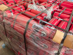
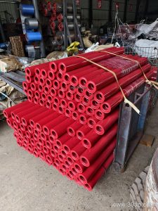
An impact idler bracket is the support frame that carries impact idlers directly beneath the loading point of a conveyor. Its job is simple to describe and demanding in practice: hold the rollers at the correct height and trough angle while absorbing the repeated shock of falling material. In a quarry, a crusher discharge, or a cement plant receiving clinker, this bracket is often the first structural component to feel the punishment of the job.
The bracket is not a wear part in the same sense as the roller shell, but it sets the geometry that determines how well the whole station performs. If the frame flexes or the mounting holes elongate, the idlers drop out of alignment, the belt sags, and spillage increases. That is why buyers should treat the bracket as an engineered component rather than a piece of bent steel.
How the Bracket Is Built
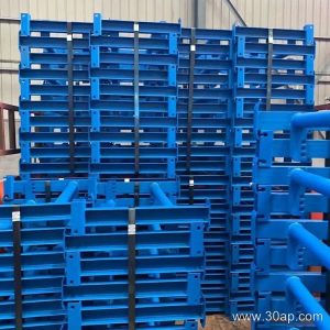
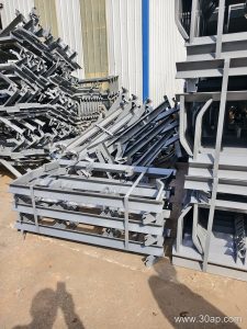
Most units are fabricated from angle steel, channel steel, or folded plate. The choice depends on belt width, load height, and the weight of the material being handled. A typical impact bracket uses a pair of side rails connected by a cross member, with slotted or drilled mounting positions for the idler shafts. Heavier designs add gussets or a reinforced center section to resist bending under surge loads.
Surface treatment matters in wet or corrosive service. Painted frames are common in general bulk handling, while galvanized or coated versions appear in ports and fertilizer plants where moisture and chemical exposure shorten service life. The bracket should be checked for squareness before installation, because a twisted frame will tilt every idler mounted on it.
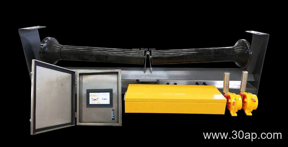
Where It Fits in the Conveyor Layout
The impact bracket is normally installed at the transfer point, just downstream of the chute. It is frequently combined with a rubber conveyor belt that has good cut and gouge resistance, since the same zone that punishes the frame also punishes the belt cover. In coal mining and power plant coal handling, flame retardant conveyor belt grades are often specified alongside these brackets for safety reasons.
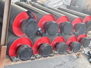
It is distinct from the carrying bracket further along the line and from the return bracket underneath. It should not be confused with the conveyor pulley at the drive or tail end, which performs a completely different function. A bend pulley or a drive pulley does not replace an impact station, and the two should never be treated as interchangeable in a layout drawing.
Matching Bracket, Belt, and Roller
Selection starts with belt width and the expected impact energy. Common reference combinations include B800 with a 35 degree trough and Ø108 idlers, or B1200 with a 45 degree trough and Ø133 rollers. These are examples, not fixed rules; the same belt width can be paired with different trough angles and roller diameters depending on the duty.
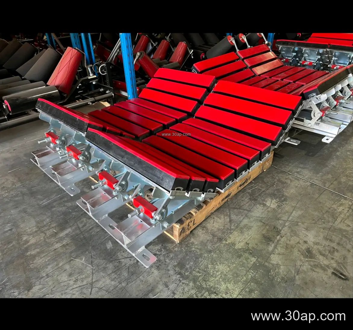
The table below groups typical reference values. Mounting hole spacing and cross member length should always be confirmed against the actual conveyor design, because they vary with width and trough angle.
| Reference Item | Common Range | Notes |
|---|---|---|
| Belt width | B500 to B2200 | Match to the existing conveyor frame |
| Trough angle | 20, 30, 35, 45 degrees | Adjustable frames cover several angles |
| Idler diameter | Ø89, Ø108, Ø133, Ø159, Ø194 | Larger rollers suit heavier lumps |
| Frame material | Angle, channel, folded plate | Thickness chosen by load class |
| Mounting | Slotted or drilled | Confirm hole pitch with supplier |
Heavy-duty mining conveyor belt installations usually call for a stiffer frame and a larger roller diameter than a sand and gravel line running the same width. For abrasive ore duties, an abrasion resistant conveyor belt paired with a robust bracket reduces the frequency of load zone repairs.
Buyer Checklist Before Ordering
- Confirm belt width, trough angle, and idler diameter as a set.
- State the material lump size and drop height so the frame class can be chosen.
- Ask whether the bracket is fixed or adjustable, since adjustable versions allow trough angle changes on site.
- Check hole pitch and cross member length rather than assuming a standard.
- Review the finish for the site environment, especially in ports or chemical plants.
For a second opinion on how the bracket fits with your belt and roller choices, the team at conveyoridler.com can review the load zone layout. Similar guidance on frame and roller matching is available through beltconveyorparts.com and conveyorroller.net for projects in iron ore, sintering, and aggregate crushing.
Installation and Maintenance Notes
Mount the bracket on a flat, clean surface and tighten fasteners evenly so the frame does not distort. After the first weeks of operation, recheck bolt torque and inspect for cracks near welds, particularly where the chute delivers large lumps. A cracked impact bracket should be replaced rather than patched, because a repair weld rarely restores the original stiffness. Keeping the impact zone in good order protects the belt, the idlers, and the structure behind them.