What a Conveyor Frame Does on a Belt Conveyor
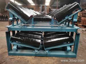
A conveyor frame is the steel backbone that holds every rotating part of a belt conveyor in the right position. It carries the idler roller sets, supports the conveyor pulley at the head and tail, and keeps the conveyor belt running in a stable line from loading point to discharge. In a quarry, a coal washing plant or a cement kiln feed line, the frame is the part that turns a loose collection of rollers and belts into a working machine.
Frames are usually built from angle steel, channel steel or folded steel plate. Light-duty frames may use bolted angle sections, while heavy-duty mining conveyor frames often use welded channel cross members. The design must resist belt tension, material impact and the vibration that comes from a loaded belt running at speed.
Main Parts of the Frame Assembly
A complete frame is more than two side rails. Typical components include:
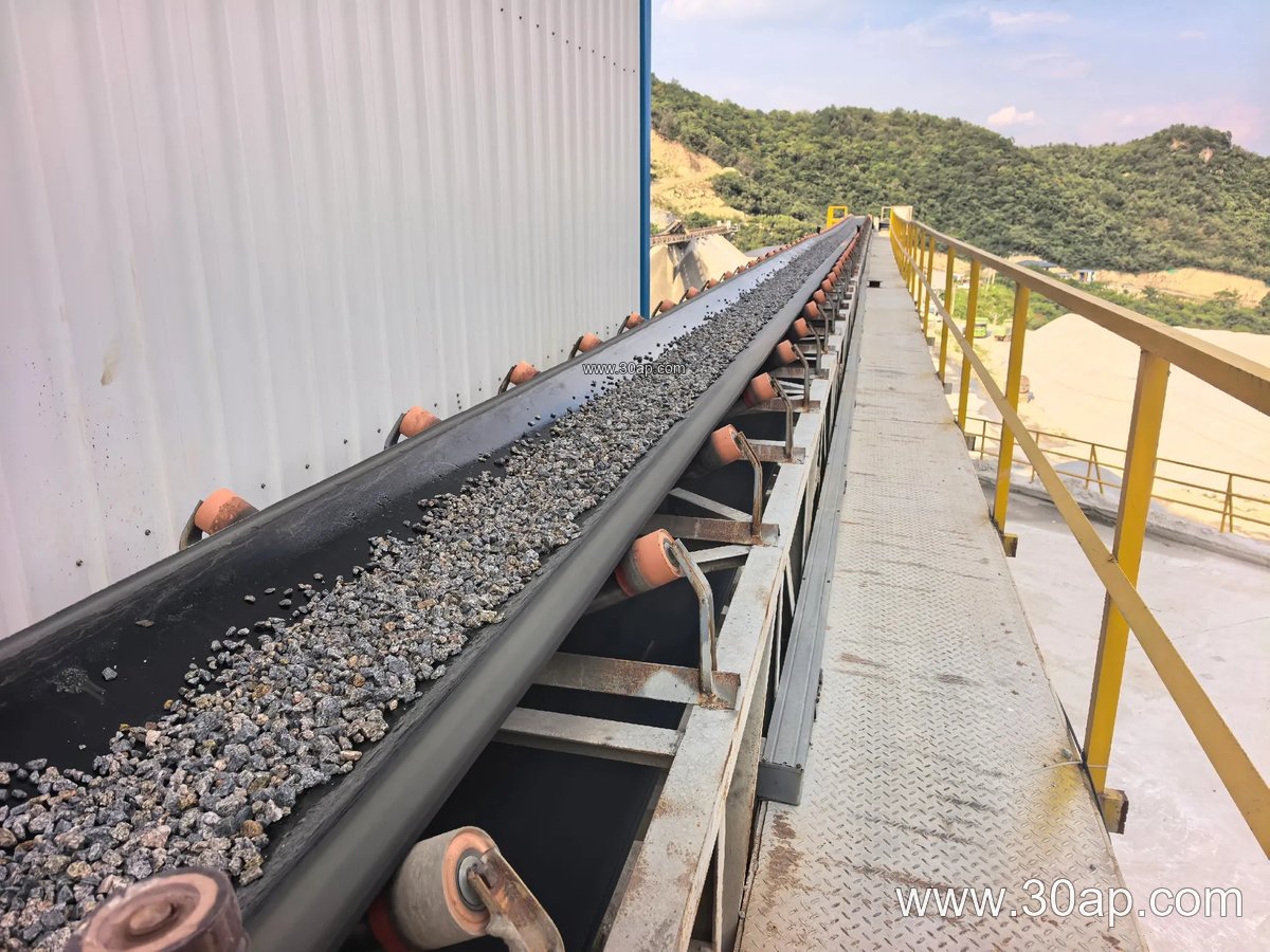
- Side rails or stringers that run the full length of the conveyor
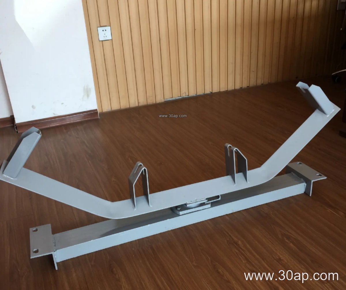
- Cross beams that carry the idler roller sets at the chosen trough angle
- Conveyor bracket plates for mounting troughing, return and impact idlers
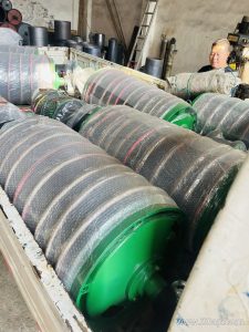
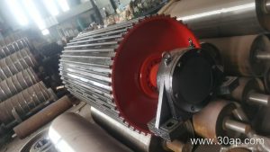
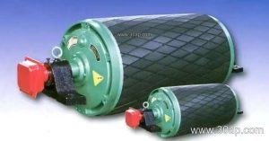
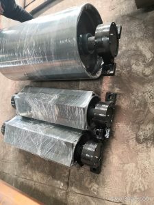
- Head and tail sections that support the drive pulley and tail pulley
- Take-up frames and bend pulley supports where the belt path changes direction
The drive pulley, tail pulley and bend pulley each need their own support geometry, so the frame around them is designed separately rather than treated as one generic part. A bend pulley frame, for example, is positioned to redirect the belt, while the tail frame must allow belt tension adjustment.
Trough Angle, Belt Width and Roller Diameter
Trough angle and belt width are linked to the frame cross beam. Common trough angles are 20, 30, 35 and 45 degrees, and adjustable frames can be set between these values. A 35 degree frame with Ø108 idlers is a frequent choice for medium-duty bulk handling, while a B1200 line in a coal plant may use 45 degrees and Ø133 rollers. These are examples, not fixed rules, because the correct combination depends on belt width, material and load.
| Frame Parameter | Common Reference Values |
|---|---|
| Belt width | B500, B650, B800, B1000, B1200, B1400, B1600, B1800, B2000 |
| Trough angle | 20°, 30°, 35°, 45° (adjustable versions cover a range) |
| Idler diameter | Ø89, Ø108, Ø133, Ø159, Ø194 |
| Material | Angle steel, channel steel, folded plate |
Installation hole spacing and cross beam length change with belt width and trough angle, so they should be confirmed from the drawing rather than assumed.
Frame Types and Where They Fit
Troughing frames carry the loaded run. Transition frames sit near the head and tail to guide the belt from flat to troughed shape. Return frames support the empty side, and V-return frames help center the belt. Impact frames with buffer idlers are placed under the loading point, while self-aligning frames correct belt drift on long runs. A spiral roller frame is used where sticky material tends to build up. Hanging frames suit confined spaces such as underground mining conveyor galleries.
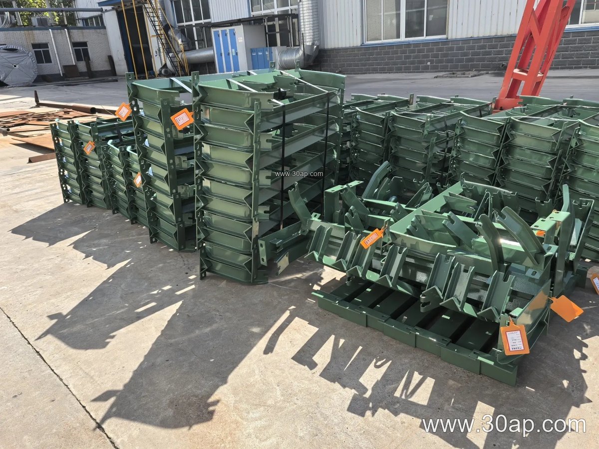
Adjustable frames allow the trough angle to be changed on site, which is useful when material flow varies. Fixed frames are simpler and stiffer, and are common on long overland lines in iron ore or copper ore transport.
Working With the Belt and Rollers
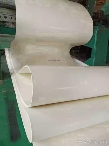
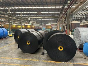
The frame must match the conveyor belt it carries. A heavy-duty mining conveyor belt or a steel cord conveyor belt needs a stiffer frame than a light fabric core belt. In a sand and gravel line, an abrasion resistant conveyor belt running over well-aligned idlers will last longer, and the frame is what keeps that alignment. Heat resistant belts in a sinter plant and flame retardant belts in an underground coal mine also rely on frames that hold position under thermal cycling and dust.
Frame selection should consider belt width, pulley diameter, load, environment and maintenance access. Checking these points before ordering saves rework during installation at mining-tool.com and belt-conveyor.com project sites.