What a Guide Idler Bracket Does
A guide idler bracket is the mounting component that holds a guide idler in position along a conveyor and keeps the belt tracking within acceptable limits. In practice, this bracket works as a locating base for the idler roller shaft, fixing its angle and height so the idler can steer the belt back toward the center line. Buyers often meet it under the equivalent name idler guide bracket, and the two terms describe the same part. It is not a substitute for a drive pulley or a tail pulley; those are separate components with different duties. The bracket is a support and alignment detail, and its job is to make the idler do its work consistently.
Construction and Mounting Position
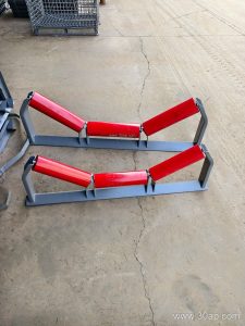
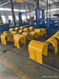
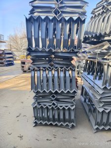
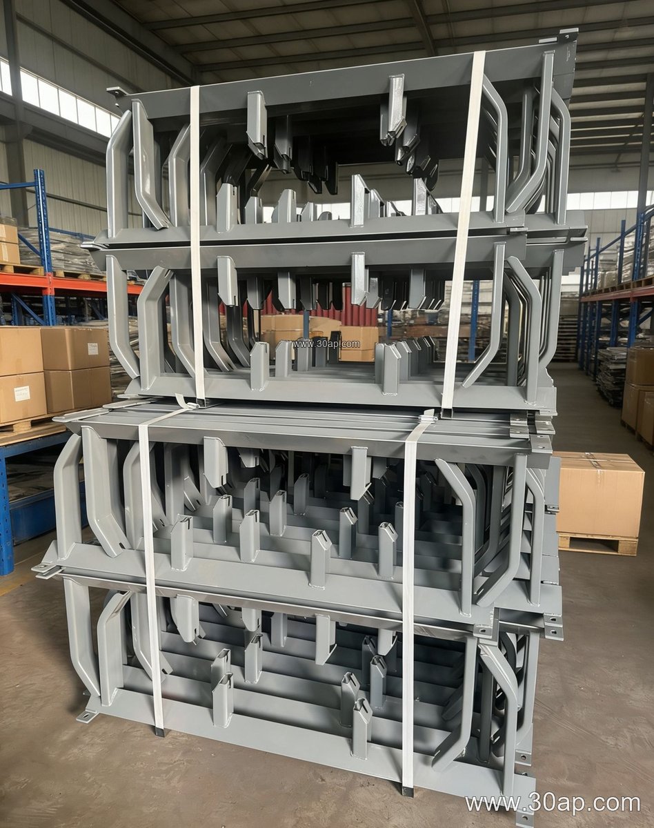
Most units are fabricated from angle steel, channel steel, or folded steel plate, then drilled for the idler shaft and for fixing to the conveyor frame. A typical assembly includes a base plate, an upright or angled face that sets the idler position, and slotted or drilled holes for adjustment. Mounting hole spacing and crossbeam length usually follow belt width and trough angle, so they are determined by design rather than taken as a fixed number.
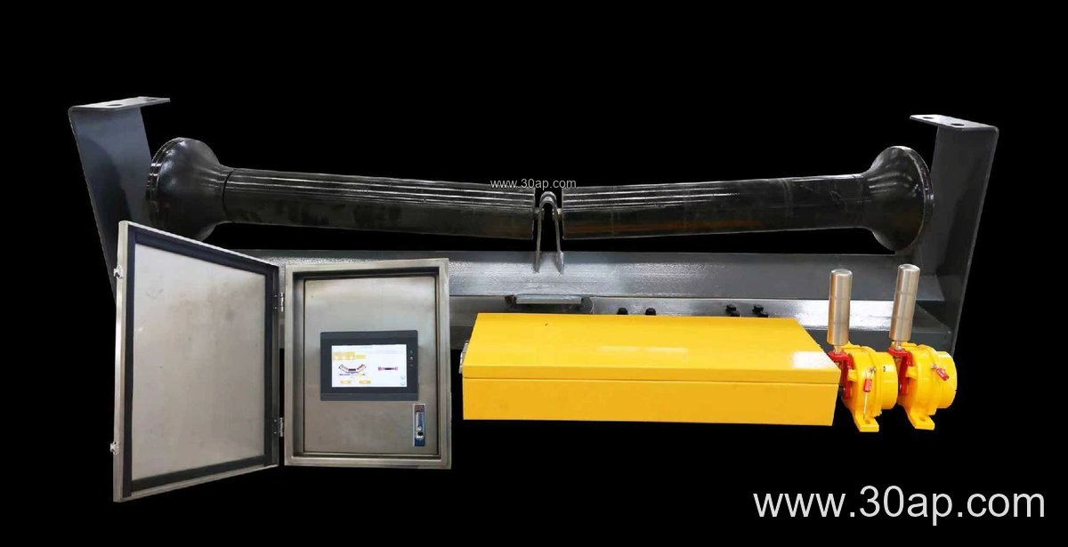
Guide brackets are commonly placed on the carrying side near loading points, on curves, or ahead of critical transfer points where misalignment is likely. On the return side, a similar bracket may hold a V-return idler. The bracket must sit square to the frame; a small twist at the base becomes a large tracking error at the belt edge.
Common Configurations
The table below groups reference configurations that appear in general conveyor design. Values are typical references and should be confirmed against the actual frame drawing.
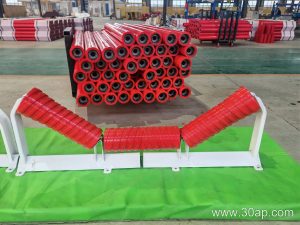
- Trough angle: 20, 30, 35, or 45 degrees; adjustable brackets can move between these positions.
- Belt width range: B500 up to B2200, with B800, B1000, B1200, and B1400 common in quarry and cement service.
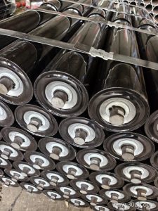
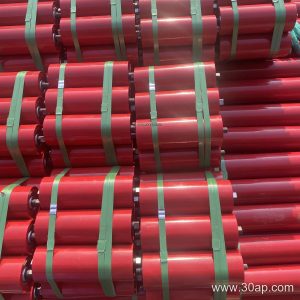
- Idler diameter: Ø89, Ø108, Ø133, Ø159, or Ø194 depending on load and belt speed.
- Forward tilt: about 1.5 to 2 degrees on leading-idler arrangements.
For example, a B800 frame with a 35 degree trough and Ø108 idlers is a familiar combination, while a B1200 line may run 45 degree troughing with Ø133 idlers. Neither pairing is mandatory, and a wider belt can carry different idler diameters depending on the duty.
Where It Fits in the Plant
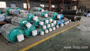
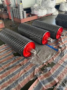
In a limestone quarry or a sand and gravel line, a guide idler bracket is often installed after the crusher discharge to control belt wander caused by uneven loading. In a coal preparation plant or a power station coal yard, the same part helps hold alignment on long transfer conveyors that carry a flame retardant conveyor belt or an abrasion resistant conveyor belt. Cement plants use them on clinker and raw meal lines, and steel plants apply them on sinter and ore conveyors. The bracket itself is small, but poor alignment shortens belt life and puts extra load on the idler roller and the conveyor pulley.
Buyer Checklist
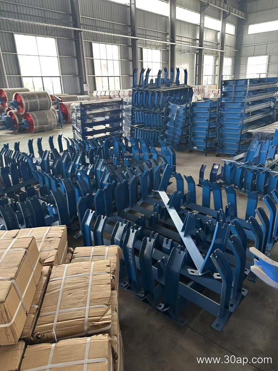
Before ordering, confirm the belt width, trough angle, idler diameter, and the shaft end size the bracket must accept. Check the frame hole pattern and the available adjustment travel. Ask whether a fixed or adjustable version suits the application: fixed brackets are simple and repeatable, while adjustable types allow fine tracking correction after installation. Confirm the material and surface treatment for the site conditions, especially in wet or dusty service.
During installation, align the bracket to the frame center line, tighten to the specified torque, and check belt tracking after the first few hours of running. Keep spare brackets on hand for wear or impact damage, and inspect welds and bolt holes at routine shutdowns. A correctly matched guide idler bracket is a low-cost way to protect the conveyor belt, the idler roller, and the whole conveyor bracket structure.