What an Intermediate Bend Pulley Does
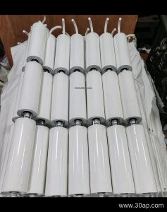
An intermediate bend pulley is a non-drive conveyor pulley that changes the path of a conveyor belt between the head and tail of the machine. It is a redirecting pulley in the true sense of the term, not a drive pulley and not a tail pulley, and the three should never be treated as interchangeable. In long or compact conveyor runs, the belt often has to be routed around structures, tensioning stations, or transfer points, and an intermediate bend pulley provides that change of direction while keeping wrap angles on the main pulleys within a workable range.
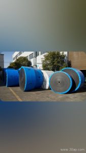
Because it carries belt tension without transmitting drive torque, this pulley is usually sized around the belt load, the wrap angle, and the surrounding structure rather than around motor power. It appears in quarry and aggregate lines, coal handling systems, cement plant clinker circuits, power plant coal conveying, and port bulk terminals, often alongside a fabric core conveyor belt or a steel cord conveyor belt depending on the duty.
Construction of the Pulley
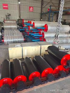
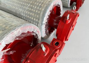
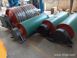
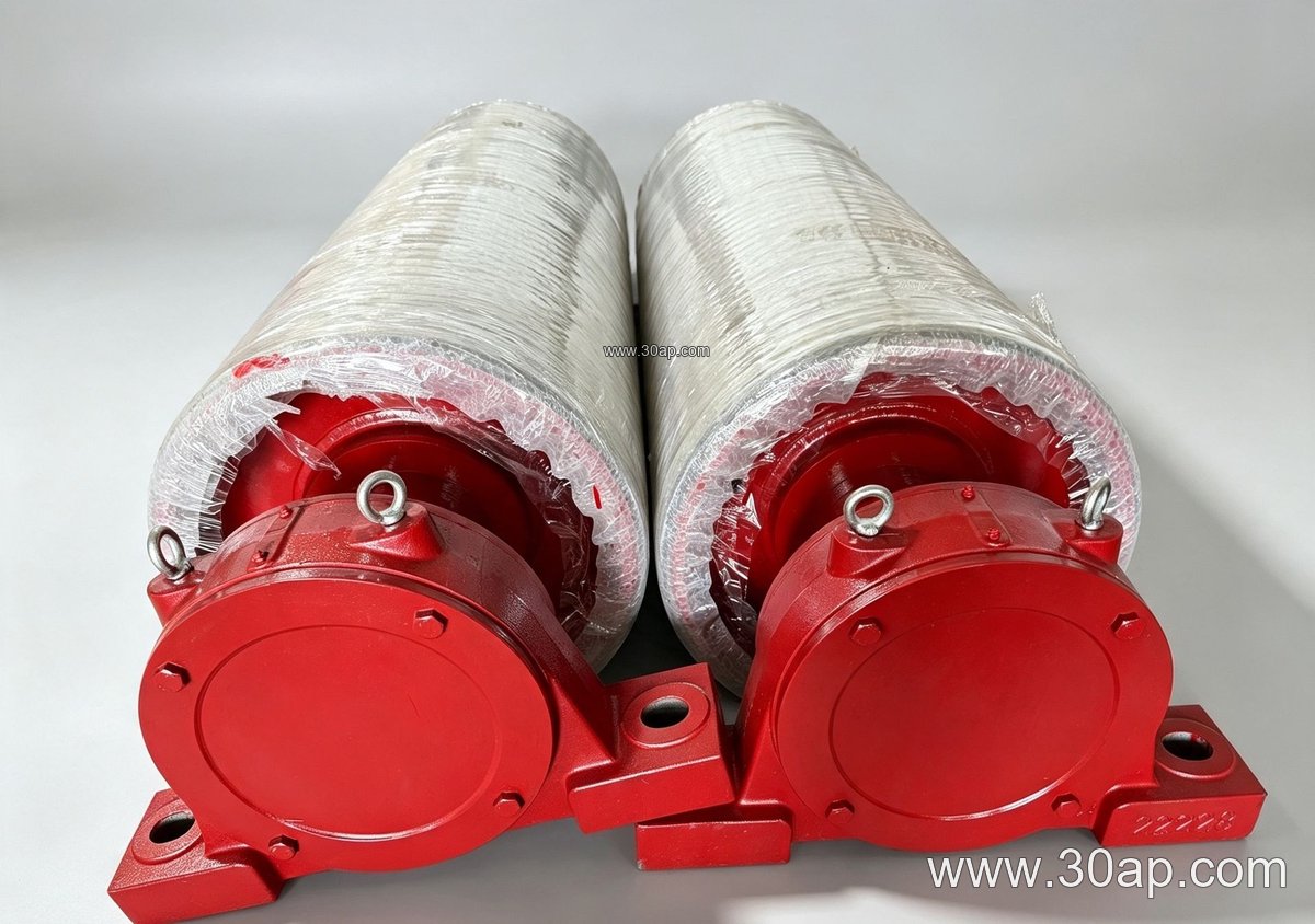
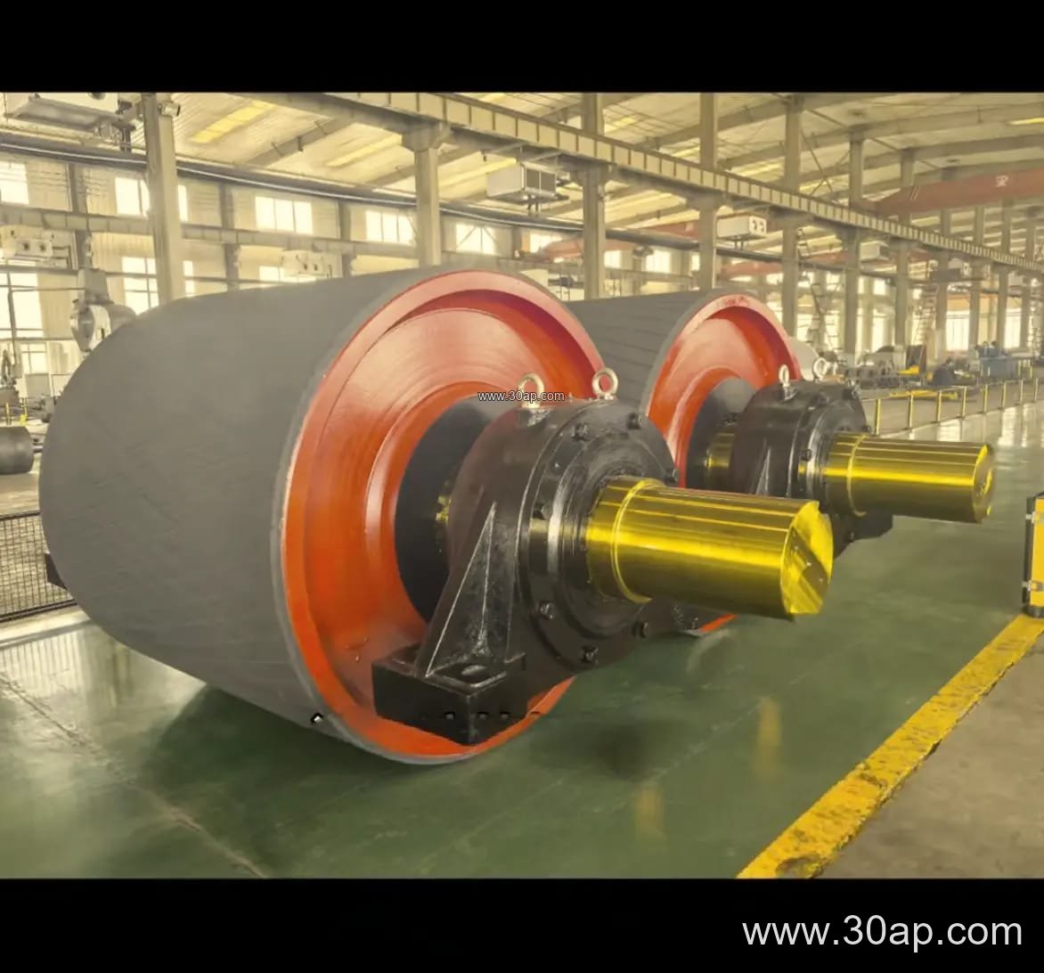
The body is typically a welded steel shell with end discs and a through shaft, supported by bearing housings that bolt to the conveyor bracket or frame. The shell surface may be plain, or it may carry rubber lagging applied by cold bonding, hot vulcanizing, or as diamond or herringbone grooving. Lagging thickness commonly ranges from 8 mm to 20 mm, with 10 mm and 12 mm being frequent choices for bend positions where slip is not a design concern but belt protection is.
Key build details that a buyer should confirm include shell wall thickness, shaft material and diameter, bearing type and sealing arrangement, and the surface finish. Shaft diameters are commonly selected from a range such as Ø50, Ø60, Ø70, Ø80, Ø90, Ø100, Ø120, Ø140, Ø160, Ø180, and Ø200 mm, but the correct value follows from torque, radial load, and bearing life calculations, not from belt width alone. A B1200 conveyor does not automatically require one fixed shaft size.
Common Sizes and Combinations
Bend pulleys are usually built to match the belt width, with the pulley face slightly wider than the belt. Typical reference combinations are shown below; these are common examples, not mandatory pairings, and a single belt width can be matched with more than one pulley diameter.
| Belt width | Typical pulley face width | Example pulley diameter | Example shaft diameter |
|---|---|---|---|
| B500 | about 600 mm | Ø250 / Ø315 | Ø60 / Ø70 |
| B650 | about 750 mm | Ø315 / Ø400 | Ø70 / Ø80 |
| B800 | about 950 mm | Ø400 / Ø500 | Ø80 / Ø100 |
| B1000 | about 1150 mm | Ø500 / Ø630 | Ø100 / Ø120 |
| B1200 | about 1400 mm | Ø630 / Ø800 / Ø1000 | Ø120 / Ø140 |
| B1400 | about 1600 mm | Ø800 / Ø1000 | Ø140 / Ø160 |
| B1600 | about 1800 mm | Ø1000 / Ø1250 | Ø160 / Ø180 |
| B1800 | about 2000 mm | Ø1250 / Ø1400 | Ø180 / Ø200 |
Larger diameters reduce belt bending stress and are often preferred where the belt is thick or stiff, for example a heavy-duty mining conveyor belt or an abrasion resistant conveyor belt with a thick cover. Small diameters save space but increase flexing, so the choice is a balance between layout and belt life.
Surface Form and Belt Interaction
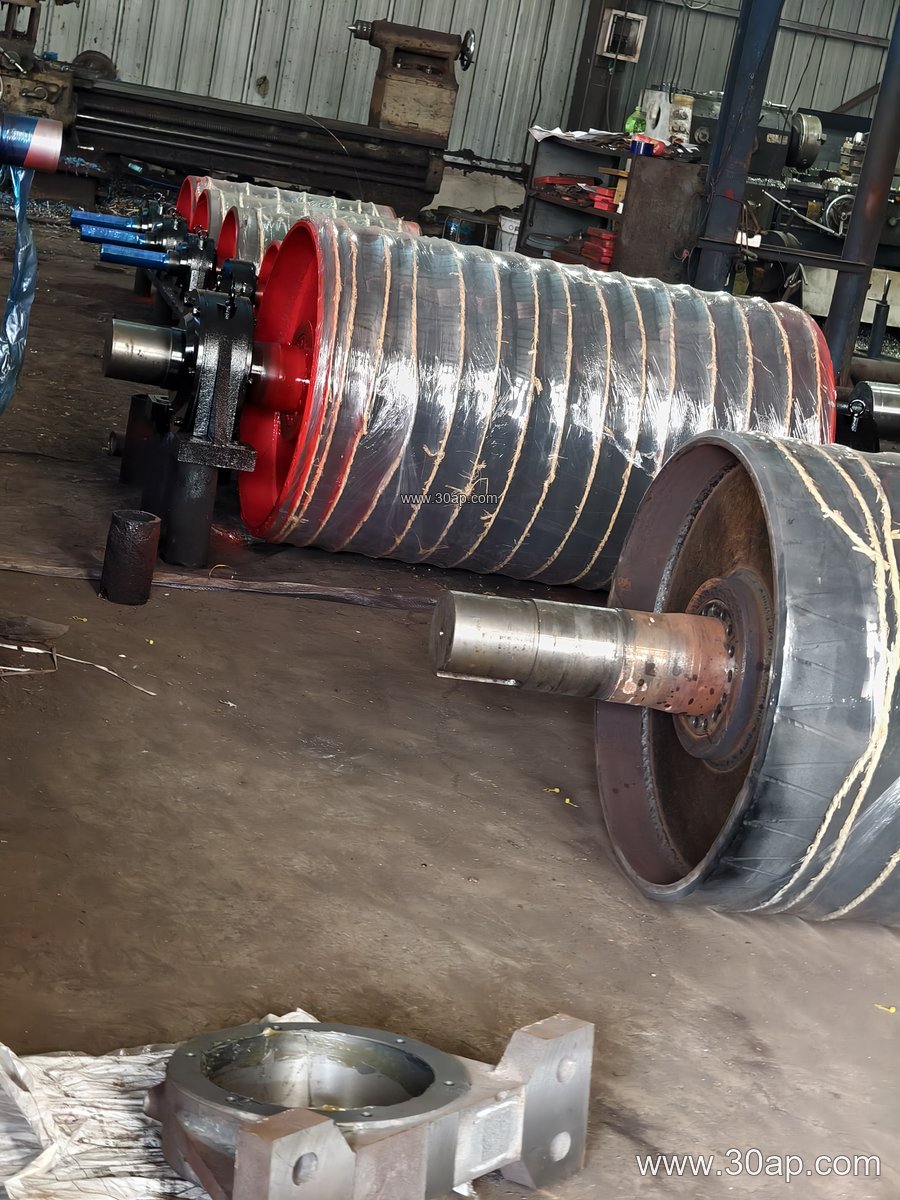
At a bend position the belt usually contacts a large arc of the pulley, so friction is less critical than at the drive pulley. Plain or lightly lagged surfaces are common. Where the belt carries sticky or abrasive material, a rubber lagging can protect both shell and belt, while a grooved surface may help shed water and fines. The pulley should be aligned with the adjacent idler roller frames so that the belt trains correctly and does not run off at the bend.
Belt selection matters as well. A pipe conveyor belt or a corrugated sidewall conveyor belt has different tracking behaviour, and a chevron conveyor belt or skirted conveyor belt may need extra clearance around the pulley. Matching the bend pulley to the belt construction avoids edge damage and premature cover wear.
Selection and Maintenance Notes
- Confirm whether the pulley is a fixed redirect, a tensioning position, or a snubber, since the duty and bearing load differ.
- Check the wrap angle and belt tension to size the shaft and bearings, rather than copying a diameter from a neighbouring conveyor.
- Specify lagging only where it adds value; over-lagging a bend pulley raises cost without improving drive performance.
- Inspect bearing seals and lagging wear at scheduled shutdowns, particularly in dusty coal or cement service.
- Keep spare bearings and fasteners compatible with the conveyor bracket and frame design.
For a complete conveyor pulley package, the intermediate bend pulley works together with the drive and tail pulleys, the carrying and return idler roller sets, and the supporting structure. Buyers comparing suppliers should ask for drawings showing shell, shaft, bearing, and lagging details, and should verify that the delivered unit matches the belt width and the layout drawing rather than a generic catalogue entry.