What a Ceramic Lagged Pulley Does on a Belt Conveyor
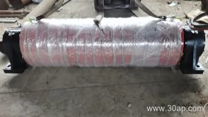
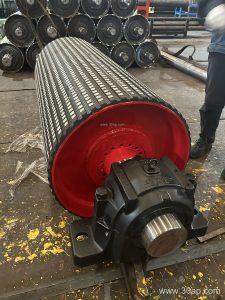
A belt conveyor ceramic lagged pulley is a conveyor pulley whose shell is covered with ceramic tiles embedded in a rubber or epoxy matrix. This surface treatment raises the friction coefficient between the pulley and the conveyor belt, reducing slip under high torque or wet, muddy conditions. It is most often specified for the drive position, where traction is critical, but the same ceramic lagging can be applied to a tail pulley when belt tracking and grip are concerns. The ceramic lagged pulley is not a substitute for a bend pulley or a take-up pulley; those positions have different duties and usually call for plain or rubber lagging.
In a quarry or aggregate line, a belt conveyor ceramic lagged pulley helps maintain consistent belt speed even when dust and water are present. In a coal preparation plant, the same ceramic surface resists wear from fine abrasive particles that would quickly polish smooth steel. The product is also found in cement plants, power plant coal handling, and port bulk terminals where reliability matters.
Construction and Surface Options
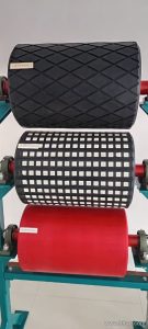
The pulley body is typically a welded steel drum with a shaft, hub, and end discs. Ceramic lagging is applied as individual tiles, usually 10–20 mm thick, bonded to the shell. The tiles have raised dimples or grooves that press into the belt cover and channel away water and fines. Common surface forms include diamond pattern and plain ceramic tile; the choice depends on belt cover hardness and the amount of carryback.
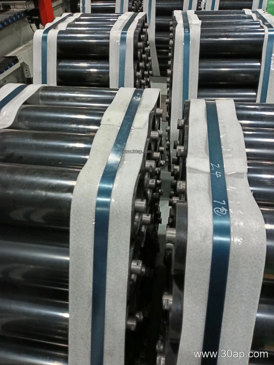
Lagging thickness is often 8, 10, 12, 15, or 20 mm. The pulley face width is normally wider than the belt. For example, a B800 belt may use a pulley face around 950 mm, while a B1200 belt may use about 1400 mm. These are reference proportions, not fixed rules; final dimensions follow the conveyor design. Shaft diameter is determined by torque and load, not by belt width alone, and common shaft sizes range from Ø50 to Ø200 mm.
Where It Fits in the Conveyor System
A belt conveyor ceramic lagged pulley is most often installed as the drive pulley at the head of the conveyor. It can also be used at the tail position when the belt is short and the load is heavy, or where the belt tends to slip on a smooth tail drum. In a crushing and screening plant, the drive pulley must handle high starting torque and frequent stops; ceramic lagging reduces belt slip and extends pulley life. At a ship loading terminal, wet coal or ore can reduce friction on plain steel, making ceramic lagging a practical choice.
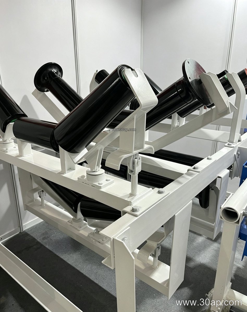
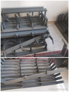
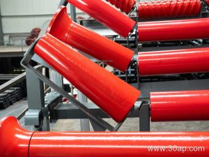
The pulley works together with the conveyor belt, idler roller, and conveyor bracket. A worn or poorly aligned idler roller can cause belt wander that no lagging can correct, so the whole system should be checked. The conveyor bracket must support the pulley shaft securely and allow for tension adjustment.
Selection and Maintenance Notes for Buyers
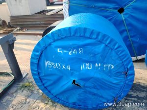
Buyers should match the ceramic lagging to the belt type and operating environment. An abrasion resistant conveyor belt with a thick cover may need a different ceramic pattern than a thin EP conveyor belt. For high-temperature service, such as in a cement plant clinker line, a heat resistant conveyor belt may be used, and the pulley lagging should be checked for temperature limits. In underground coal mining, a flame retardant conveyor belt is common, and the pulley should be selected with fire safety in mind. A steel cord conveyor belt requires a pulley with sufficient diameter to avoid excessive bending stress; the ceramic lagging does not change that requirement.
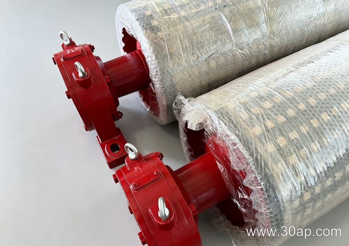
Maintenance is simple: inspect the ceramic tiles for cracks or missing pieces, check the bond line for separation, and clean the surface if material buildup occurs. A damaged tile can be replaced individually in many designs. Keep the belt tension correct and align the conveyor pulley with the belt to prevent edge wear. Record the pulley size and lagging thickness for future replacement.
Common Reference Dimensions
The table below shows typical combinations, not mandatory pairings. Use it as a starting point for discussion with a conveyor designer.
| Belt Width | Typical Pulley Face Width | Example Pulley Diameter |
|---|---|---|
| B500 | About 600 mm | Ø250 or Ø315 |
| B650 | About 750 mm | Ø315 or Ø400 |
| B800 | About 950 mm | Ø400 or Ø500 |
| B1000 | About 1150 mm | Ø500 or Ø630 |
| B1200 | About 1400 mm | Ø630 or Ø800 |
| B1400 | About 1600 mm | Ø800 or Ø1000 |
Larger diameters are available for high-tension belts. Shaft size, bearing selection, and hub design are confirmed by the manufacturer based on actual load calculations.
For more information on matching pulleys with conveyor belts and idler rollers, visit conveyor pulley and conveyor belt resources. Always confirm dimensions and lagging type with the conveyor system designer before ordering.