What a Belt Guide Roller Does on a Conveying Line
A belt guide roller is a small but decisive component in keeping a conveyor belt running true. Rather than carrying the full load like a standard carrying idler roller, this roller is positioned to touch the belt edge or to steer it back on track when slight misalignment appears. In quarry, cement plant and power plant coal handling circuits, a well-placed belt guide roller can reduce edge damage, spillage and the frequent shutdowns that follow a wandering belt. It is often used together with self-aligning idler sets, but it performs a distinct job: guiding rather than load support.
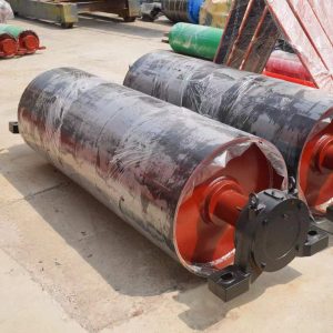
The same product is also called a belt guiding roller or conveyor belt guide roller. These are accurate equivalents for the same item, not names for a drive pulley, tail pulley or bend pulley, which are entirely different components in the conveyor pulley family.
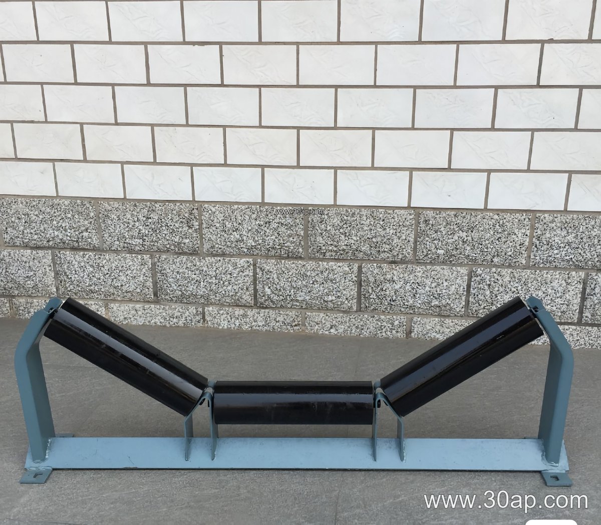
Construction and Common Surface Forms
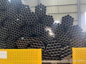
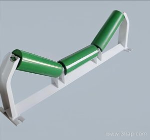
Most belt guide rollers follow the familiar roller build: a steel tube body, bearing housings at each end, a shaft, and a sealing arrangement to keep dust and water out. Bearing sizes such as 6204, 6205, 6305 and 6308 are common in this class of roller, although the correct bearing for a given guide roller depends on the shaft and load design, not on belt width alone.
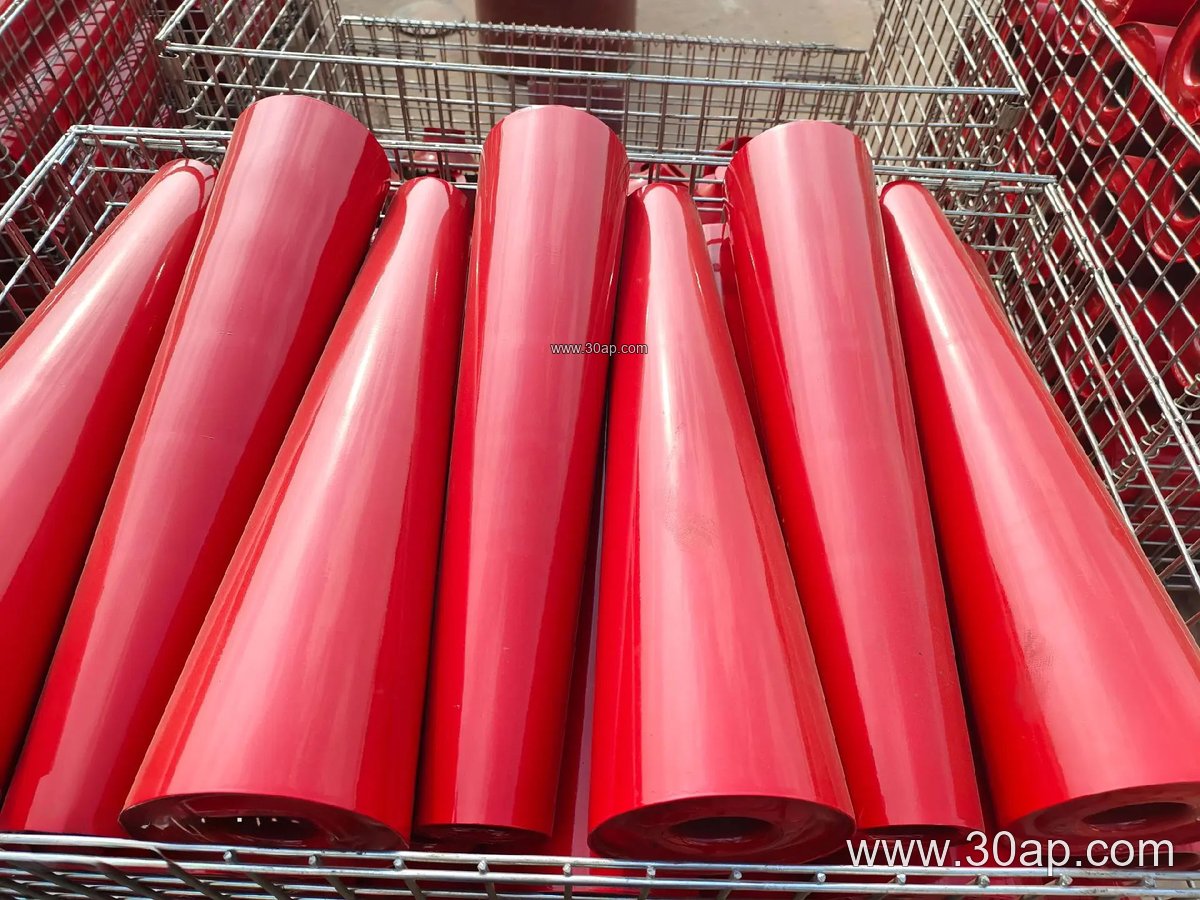
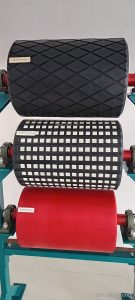
Surface options matter in abrasive or sticky service. Plain steel suits general duty, while a rubber-covered or ceramic-faced guide roller can improve grip and resist wear in stone crushing and aggregate lines. Nylon surfaces are sometimes chosen where build-up is a concern. The table below shows typical reference ranges, not fixed combinations.
| Parameter | Common reference values |
|---|---|
| Roller diameter | Ø63, Ø76, Ø89, Ø102, Ø108, Ø127, Ø133 mm |
| Belt width served | B400, B500, B650, B800, B1000, B1200, B1400 mm |
| Roller surface | Steel tube, nylon, ceramic, rubber ring |
| Bearing examples | 6204, 6205, 6305, 6306, 6308 |
| Mounting | Conveyor bracket or adjustable guide frame |
Guide roller length is set by belt width and by the mounting position, so it should be confirmed against the frame drawing rather than assumed from a single dimension.
Where It Fits in Mining and Bulk Handling
In an underground coal mining conveyor, a belt guide roller is often mounted just ahead of a transfer point or near the tail area where the belt is most likely to shift. In a limestone quarry or sand and gravel plant, the same roller helps protect the belt edge on long inclined runs. It is equally at home in a steel plant sintering line or a fertilizer handling system where dust and fines are present.
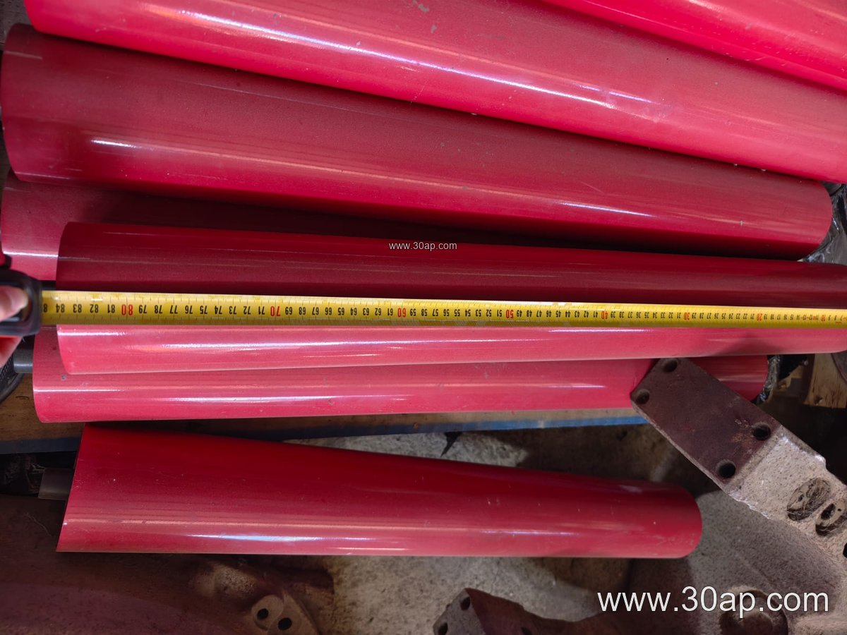
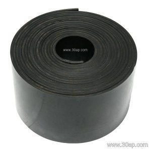
Because the guide roller contacts the belt edge, matching it to the belt construction matters. A heavy-duty abrasive resistant conveyor belt used on iron ore or copper ore duty will tolerate more edge pressure than a lighter fabric core belt. On lines carrying hot clinker or sinter, a heat resistant conveyor belt may need a guide roller positioned slightly differently to avoid concentrated contact. Where a flame retardant conveyor belt or fire resistant conveyor belt is specified for underground service, the guide roller and its mounting should follow the same safety logic as the rest of the installation.
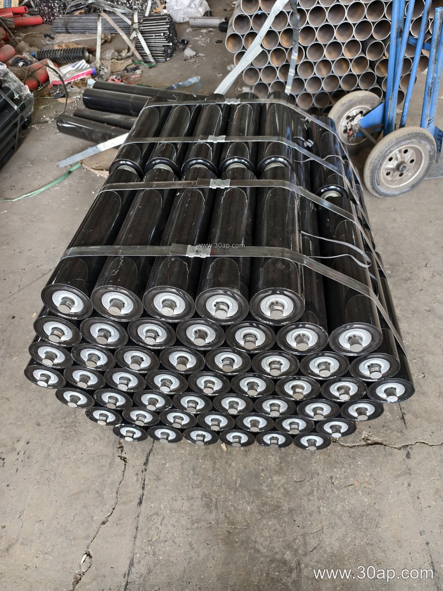
Selection Points Buyers Should Check
- Belt width and roller length: confirm the guide roller length against the frame drawing for B650, B800 or B1000 belts, since side guides and center guides differ.
- Roller diameter: a larger diameter such as Ø108 or Ø127 turns more slowly and can suit high-speed lines, while Ø76 or Ø89 is common on smaller frames.
- Surface and sealing: dusty quarry or cement service favors effective seals; wet washing circuits may call for better water exclusion.
- Mounting hardware: check that the conveyor bracket or adjustable arm allows fine lateral adjustment.
- Belt type interaction: an EP conveyor belt, NN conveyor belt or steel cord conveyor belt each responds differently to edge contact, so discuss the belt specification with the roller supplier.
Buyers should also confirm whether the guide roller works with the existing self-aligning idler roller arrangement, and whether the conveyor pulley and take-up are already correctly aligned. A guide roller cannot compensate for a badly skewed drive pulley or an overloaded belt.
Installation and Maintenance Notes
Mount the belt guide roller so it touches the belt only when a small deviation occurs, not continuously under heavy pressure. Check rotation by hand after installation and confirm the roller turns freely. During routine inspections, look for flat spots, worn surfaces and seized bearings, and re-check alignment after any belt splicing or frame repair. In coal mining and underground mining conveyor systems, keep the guide roller clear of accumulated material, since build-up can push the belt in the wrong direction.
For plant engineers sourcing replacement parts, a clear drawing with belt width, roller diameter, shaft detail and bracket type will usually speed up the match. More conveyor component references are available at mysite.example/belt-guide-roller and mysite.example/conveyor-pulley for related drive and tail pulley information.