Understanding the Role of Pulley Lagging in Bulk Material Handling
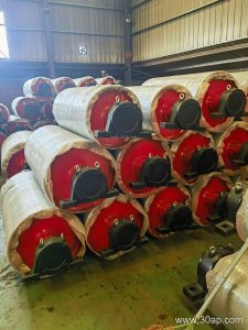
In demanding industrial environments such as a modern cement plant or a busy Steel Plant Conveyor Belt layout, maintaining reliable frictional grip between the driving component and the moving conveyor belt is vital. Applying a protective and high-friction outer layer to the cylindrical shell significantly enhances power transmission, reduces slippage, and protects the underlying metal structure from premature wear. While a standard bare steel shell can handle moderate loads, heavy-duty applications demand specialized surface treatments to perform under wet, abrasive, or high-torque conditions.
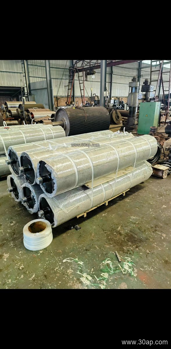
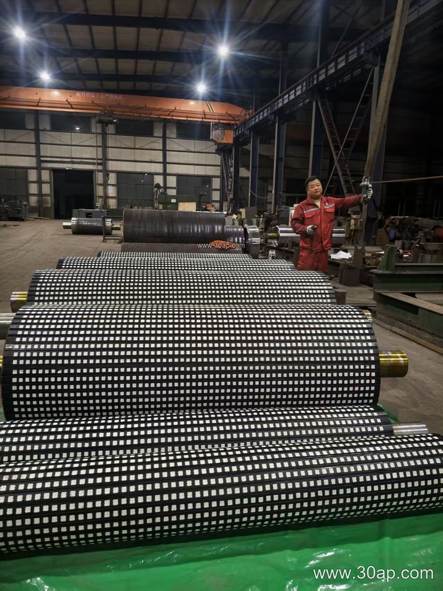
Surface Options and Their Structural Characteristics
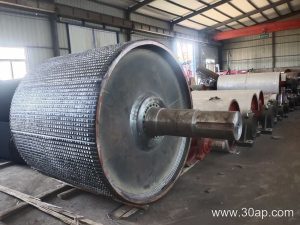
Choosing the correct surface pattern and material depends heavily on operational demands and environmental exposure. Engineers select various textures to optimize water shedding and maximize grip. For instance, ceramic tiles embedded in rubber offer exceptional wear resistance in high-impact zones, whereas grooved rubber patterns effectively channel away moisture and fine dust. The selection typically involves several distinct surface styles:
- Plain or flat rubber surface for general, low-tension applications
- Diamond grooved rubber for bidirectional movement and good water dispersion
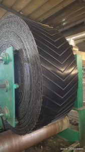
- Herringbone or chevron pattern for high-tension Heavy-Duty Conveyor Belt drives requiring maximum traction
- Ceramic-faced lagging utilizing high-alumina tiles for extreme abrasive wear environments
Technical Specifications and Dimension References
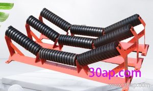
Lagging thickness and shell dimensions must align with the mechanical design of the conveyor assembly, working alongside components like the conveyor pulley, idler roller, and structural conveyor bracket. Standard engineering references outline various common dimensions used in heavy-duty design, though exact configurations always depend on specific load calculations and torque requirements rather than rigid formulas.
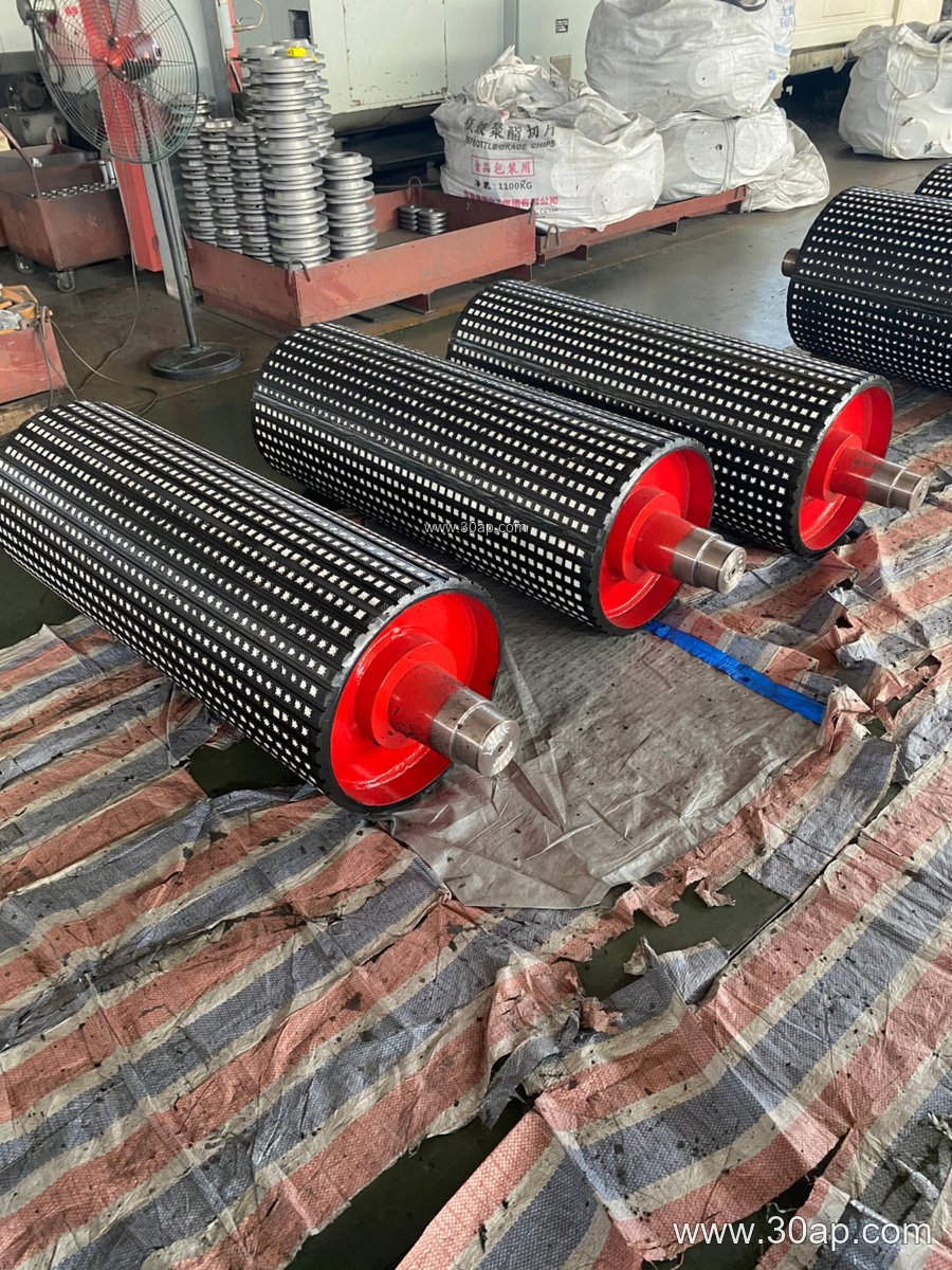
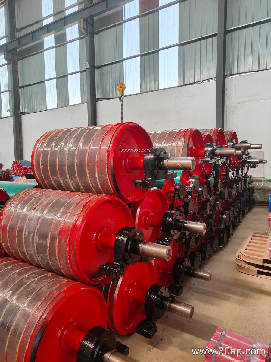
| Bandwidth Reference | Shell Width Reference | Common Diameter Options | Typical Lagging Thickness |
|---|---|---|---|
| B650 | Approx. 750 mm | Ø400, Ø500, Ø630 | 8, 10, 12 mm |
| B800 | Approx. 950 mm | Ø500, Ø630, Ø800 | 10, 12, 15 mm |
| B1000 | Approx. 1150 mm | Ø630, Ø800, Ø1000 | 10, 12, 15, 20 mm |
| B1200 | Approx. 1400 mm | Ø800, Ø1000, Ø1250 | 12, 15, 20 mm |
| B1400 | Approx. 1600 mm | Ø1000, Ø1250, Ø1400 | 15, 20 mm |
Furthermore, internal shafts are engineered according to the applied torque and radial loads rather than being derived solely from the belt width. Common shaft diameter sizes found in engineering designs include Ø90, Ø100, Ø120, Ø140, Ø160, and Ø180 mm.
Application Suitability in Cement Plants
Within a typical cement plant handling abrasive clinker and raw limestone, drive assemblies equipped with high-performance vulcanized rubber or ceramic lagging ensure continuous operation without unexpected stoppages. By preventing slippage between the drive shell and the traction medium, maintenance teams can extend the service life of both the driving unit and the running belt, minimizing downtime and stabilizing overall output.