What a Non-Standard Conveyor Bracket Really Is
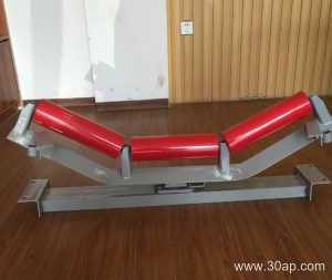
A non-standard conveyor bracket is a support component made to fit a conveyor line that does not follow a catalog drawing. Standard brackets come in fixed hole spacings, fixed beam lengths and fixed trough angles. When the structure, the transition zone or the available space does not match those figures, the bracket has to be designed around the actual installation. In practice this means the bracket is defined by the frame it must sit on, the conveyor belt width it carries, the idler diameter it accepts and the trough angle the load needs.
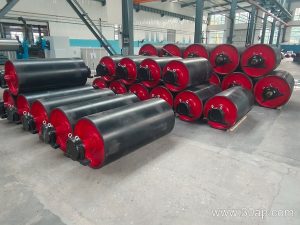
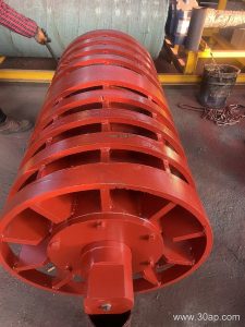
It is still a bracket, not a pulley and not an idler. A drive pulley, a tail pulley and a bend pulley all do different work and cannot replace it, and neither can a return roller. The bracket is the interface between the steel structure and the rotating parts.
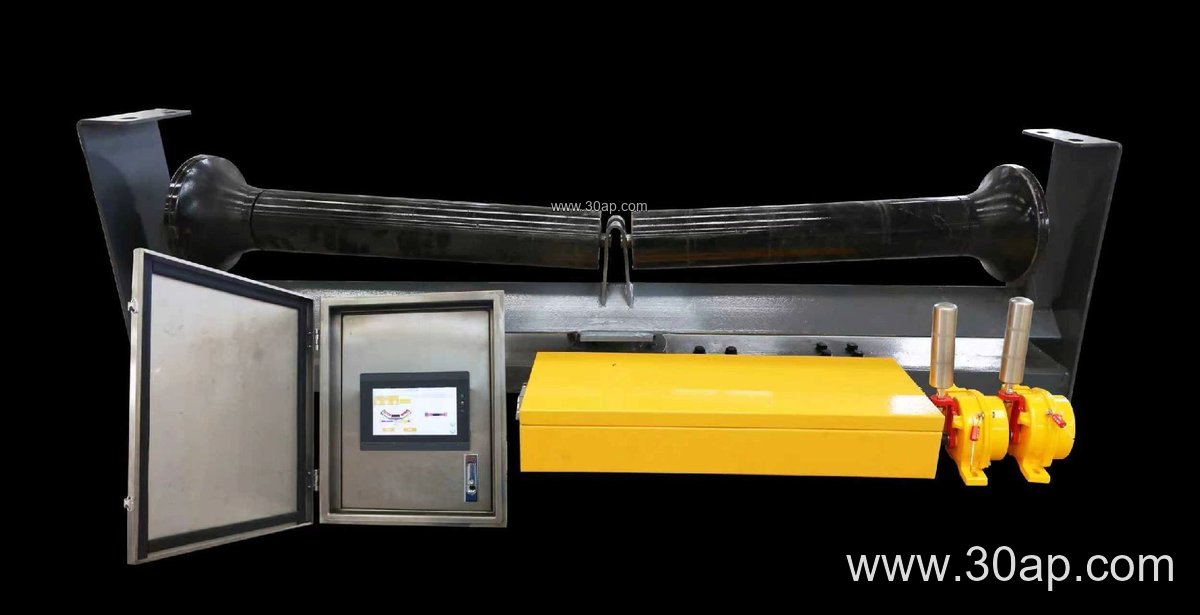
How the Bracket Is Built
Most units are fabricated from angle steel, channel steel or folded steel plate, then drilled or punched for the idler shaft and bolted or welded to the conveyor frame. Because the geometry is project-specific, the drawing usually starts from the frame rather than from a catalog page. Three values drive the design:
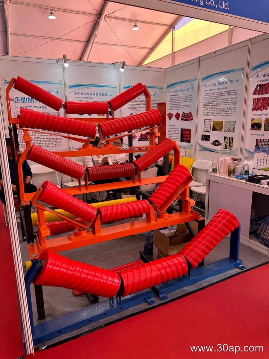
- Belt width, for example B650, B1000 or B1400, which sets the beam length and the span between side frames.
- Trough angle, commonly 20, 30, 35 or 45 degrees; adjustable brackets can move between these positions.
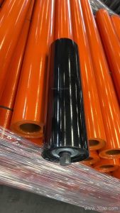
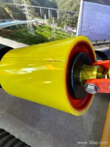
- Idler diameter, such as Ø89, Ø108, Ø133, Ø159 or Ø194, which sets the cradle height and the mounting slot.
Mounting hole spacing and crossbeam length are not fixed numbers. They change with belt width, trough angle and frame design, so they are confirmed on the drawing. A 30 degree bracket and a 45 degree bracket for the same belt width will not share the same geometry. Forward-leaning brackets, often around 1.5 to 2 degrees, are a separate detail again and are usually specified only where belt training is a concern.
Where Non-Standard Brackets Earn Their Place
These parts show up wherever the conveyor is not a clean, repeatable run. A limestone quarry might need a transition bracket between the flat tail area and the first full trough station, where the conveyor belt has to open gradually. A cement plant may need a reinforced impact bracket under a transfer chute where lump material lands hard. A coal handling system in a power plant often needs brackets that clear a walkway, a cable tray or a structural beam that was not in the original layout.
Other typical cases include crusher discharge points in a stone crushing line, ship loading booms at a port, and tunnel spoil conveyors where space is tight and frames are built on site. In each case the bracket is designed around an obstruction or a load condition, not chosen from a list.
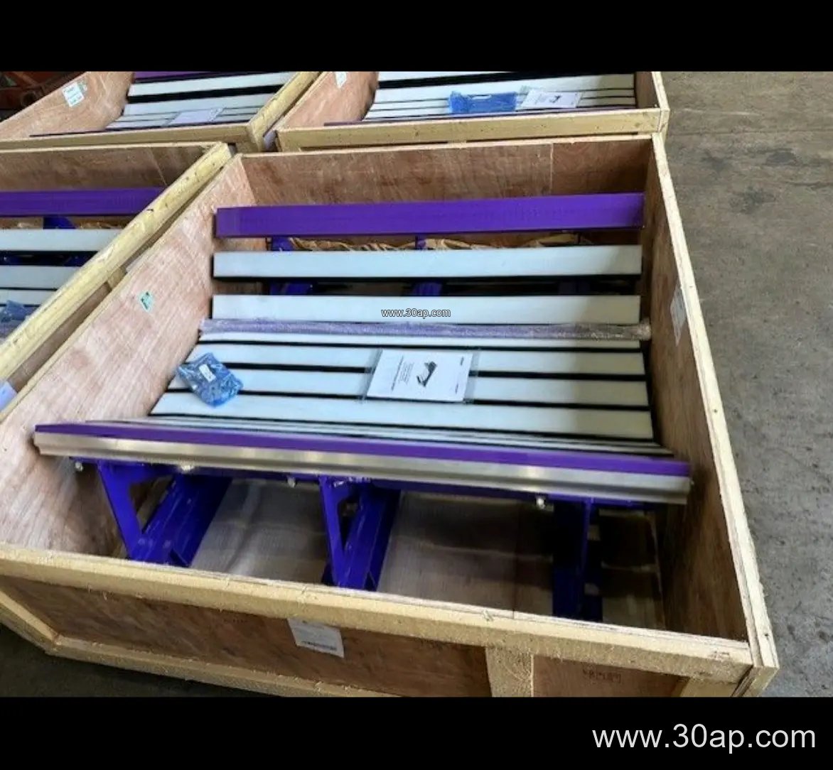
Adjustable Versus Fixed
A fixed bracket holds one trough angle for the life of the installation. An adjustable bracket lets maintenance staff change the trough angle within a range, which is useful during commissioning or when the material changes. Adjustable designs cost more and add a small number of wearing points, so they are usually reserved for lines where the belt profile is expected to be tuned. For a stable, well-understood run, a fixed bracket is simpler and stiffer.
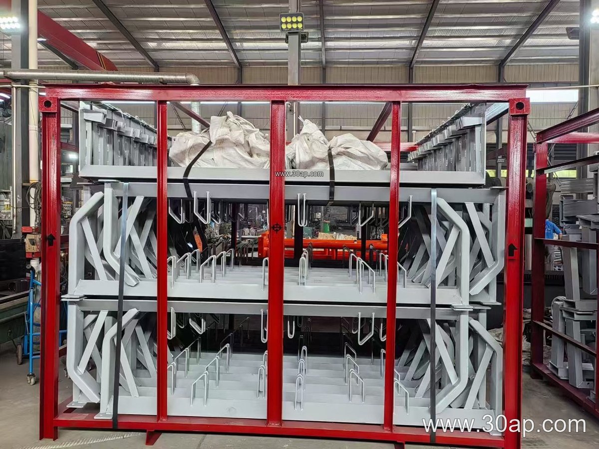
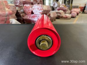
The bracket also has to work with its neighbors. A conveyor idler set sits in the cradle, the belt rides on the rollers, and the bracket transfers that load into the frame. If the bracket is weak or the hole spacing is wrong, the idlers tilt, the belt tracks poorly and edge wear follows.
Matching the Bracket to the Belt and Idlers
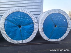
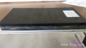
A bracket is only one part of the assembly, so the specification should be read together with the belt and roller selection. On a heavy-duty mining conveyor carrying abrasive ore, a wider belt such as B1200 or B1400 with a 35 or 45 degree trough and Ø133 or Ø159 idlers is a common combination, but it is not a rule. A lighter aggregate line on B800 may use 30 degrees and Ø108. Belt construction matters too, since a stiff steel cord belt and a flexible multi-ply fabric belt do not bend into a trough in the same way.
| Parameter | Common Range | Notes |
|---|---|---|
| Belt width | B500 to B2200 | Beam length follows the frame |
| Trough angle | 20, 30, 35, 45 degrees | Adjustable versions cover a range |
| Idler diameter | Ø89 to Ø194 | Cradle height depends on it |
| Material | Angle, channel, folded plate | Selected by load and environment |
| Mounting | Bolted or welded | Hole spacing per drawing |
Buyers should send the frame drawing, the belt width, the intended trough angle, the idler diameter and the load per station. If corrosion or heat is a factor, say so, because that affects material and coating. Ask for the hole spacing and beam length in writing rather than assuming a standard figure. A bracket that fits the frame and the idlers on the first attempt saves a shutdown later.