What the head pulley does on a conveyor
The belt conveyor head pulley sits at the discharge end of the conveyor and does two jobs at once. It drives the conveyor belt through friction between its lagged surface and the belt’s inner carcass, and it sets the point where material leaves the belt. Because it carries the highest belt tension in most installations, this component is often called the drive pulley or discharge pulley, and both names describe the same unit. It is not a tail pulley, a bend pulley, or a tensioning pulley, and those parts cannot be swapped for it.
In a quarry, coal preparation plant, cement works, or power station coal handling line, the head pulley is usually the largest pulley on the conveyor. Its diameter and shell width are chosen together with the belt width, the duty cycle, and the torque the drive must transmit.
Construction and main parts
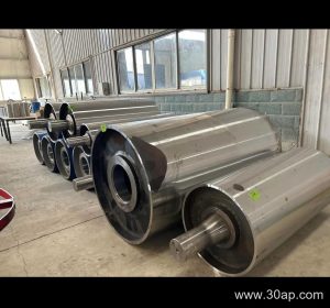
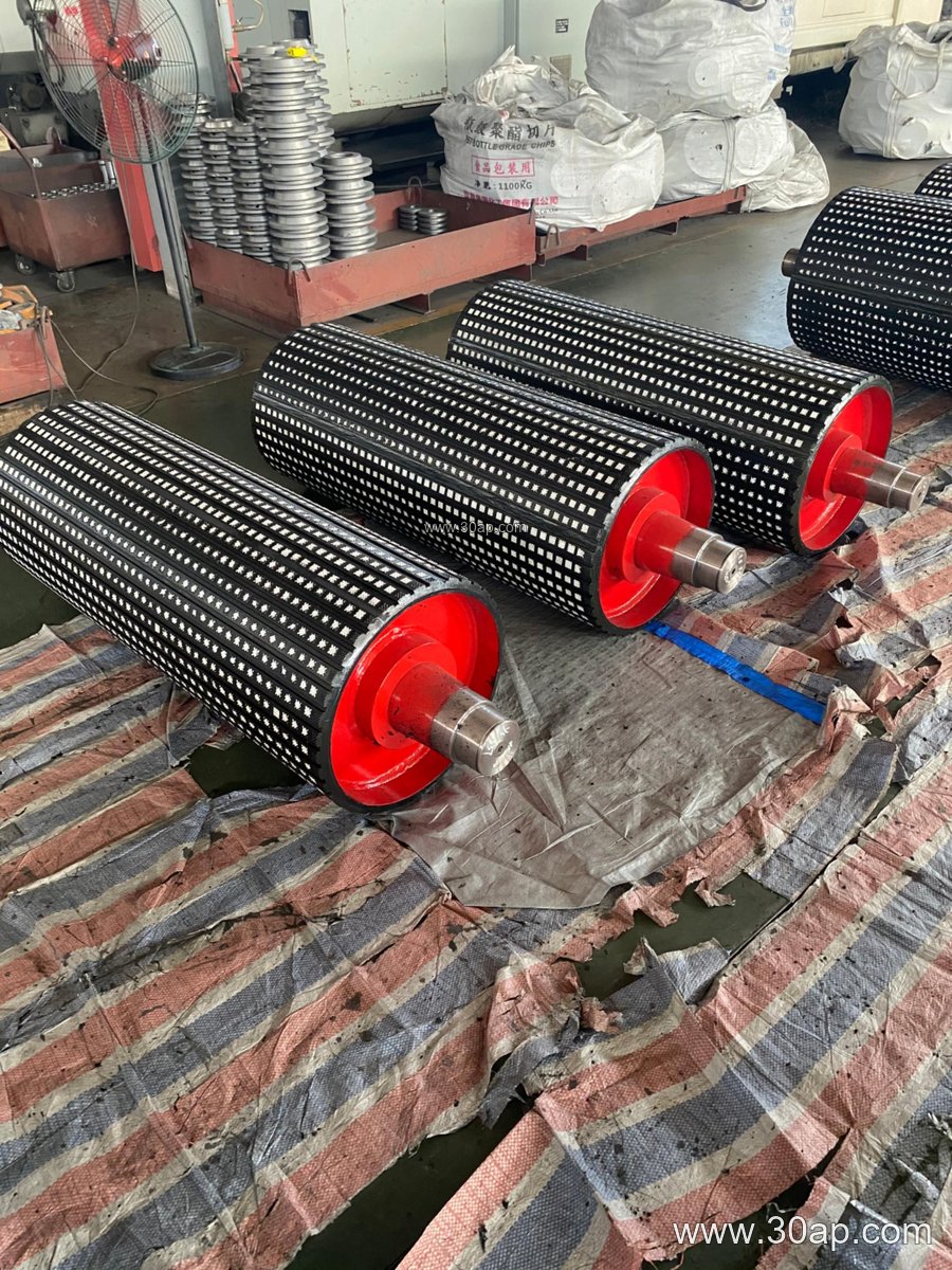
A typical belt conveyor head pulley is built around a welded steel shell with end discs, a shaft, and bearing housings that bolt to the conveyor bracket. The shell may be smooth or covered with rubber or ceramic lagging to raise friction and protect the belt. Shaft ends are keyed or shrink-fitted to the drive coupling or gearbox. Common shaft diameters include Ø80, Ø100, Ø120, Ø140, and Ø160, but the final value follows torque and bearing load rather than belt width alone.
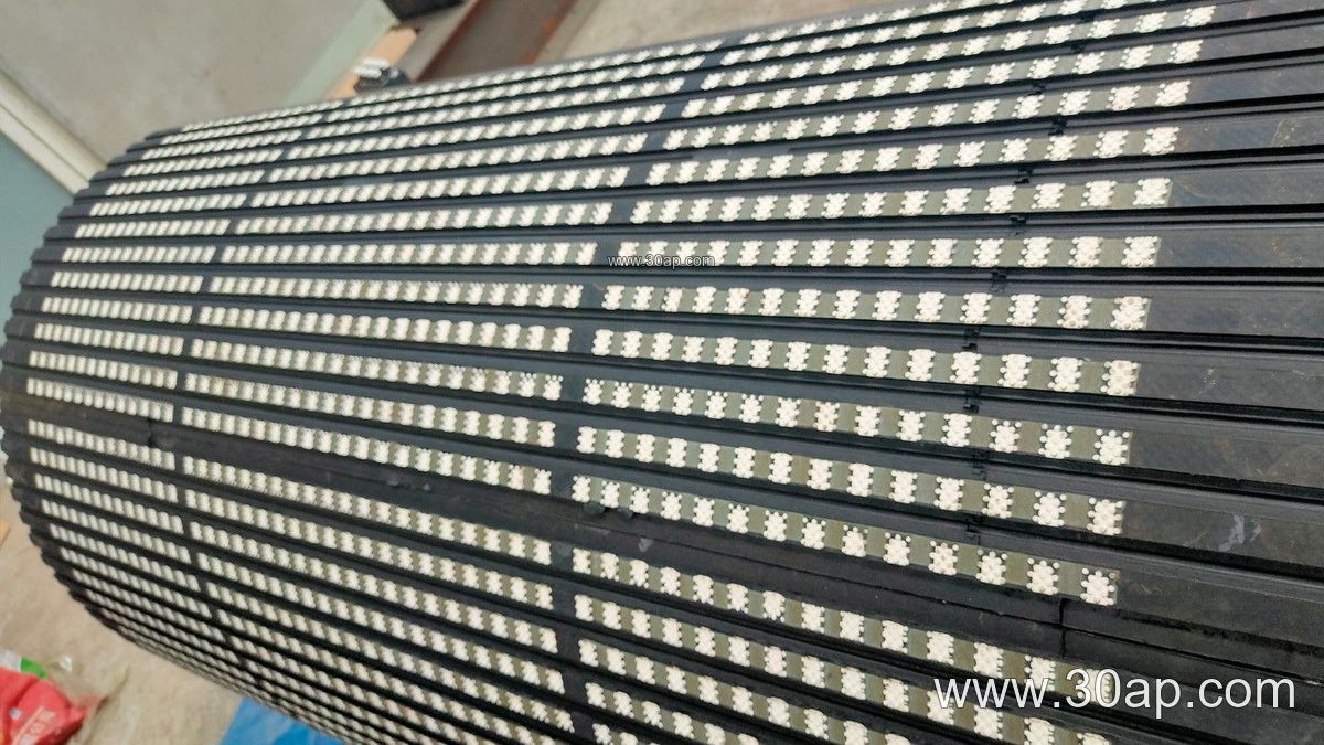
- Shell: rolled and welded steel, machined for balance
- Lagging: smooth, cast rubber, cold-bonded rubber, hot-vulcanized rubber, diamond or herringbone pattern, or ceramic
- Shaft: sized for bending and torsional load
- Bearings: pillow block or flanged housings on a fabricated frame
- Drive connection: keyed shaft, coupling, or integrated motor
Common dimensions and surface options
The shell face is normally wider than the belt so the belt is fully supported. Typical face widths run from about 500 mm for B400 up to roughly 2200 mm for B2000. Diameters commonly range from Ø200 to Ø1000, with larger sizes for heavy duty. These figures are reference points only; each conveyor design sets its own combination.
| Belt width | Typical face width | Example diameter |
|---|---|---|
| B500 | about 600 mm | Ø315 or Ø400 |
| B800 | about 950 mm | Ø500 or Ø630 |
| B1000 | about 1150 mm | Ø630 or Ø800 |
| B1200 | about 1400 mm | Ø800 or Ø1000 |
| B1400 | about 1600 mm | Ø1000 or Ø1250 |
Lagging thickness is usually 8, 10, 12, 15, or 20 mm. Rubber lagging gives reliable grip in wet or dusty conditions, while ceramic lagging suits abrasive service in iron ore or sinter plants. Diamond and herringbone patterns help shed water and fines.
Where it fits in the plant
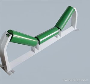
Head pulleys appear in crushing and screening circuits, aggregate stockpile conveyors, clinker lines, coal yard belts, and port bulk terminals. On a long overland conveyor, the drive pulley may be paired with a bend pulley to increase wrap angle, but the bend pulley does not replace the head pulley. The belt, conveyor idler rollers, and brackets all interact with it, so alignment matters as much as the pulley itself.
What buyers should check
- Confirm the required shaft torque and belt tension before choosing diameter.
- Match shell face width to the belt width, not to the frame width.
- Choose lagging for the actual material and moisture conditions.
- Check bearing type, lubrication method, and mounting bracket dimensions.
- Ask for balance and runout data, and verify the shaft keyway matches the drive coupling.
A well matched belt conveyor head pulley keeps the belt tracking straight, reduces slip at the drive, and gives a clean discharge point. Buyers should treat catalog sizes as a starting reference and have the final geometry confirmed against the conveyor’s tension and torque calculations.