What Conveyor Pulley Machining Involves
Conveyor pulley machining is the set of turning, boring, welding, and finishing operations that turn a steel shell, shaft, and end disc assembly into a true-running component for a belt conveyor. In a gravel aggregate line or a coal handling plant, a pulley that is out of round or has poorly aligned bearing seats will shorten belt life and cause tracking problems, so the machining stage matters as much as the material selection.
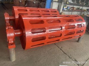
The work covers the drum surface, the shaft journals, the hub bore, and the end disc faces. A machined conveyor pulley must run concentrically, hold its balance at operating speed, and present a smooth surface for the conveyor belt to wrap around.
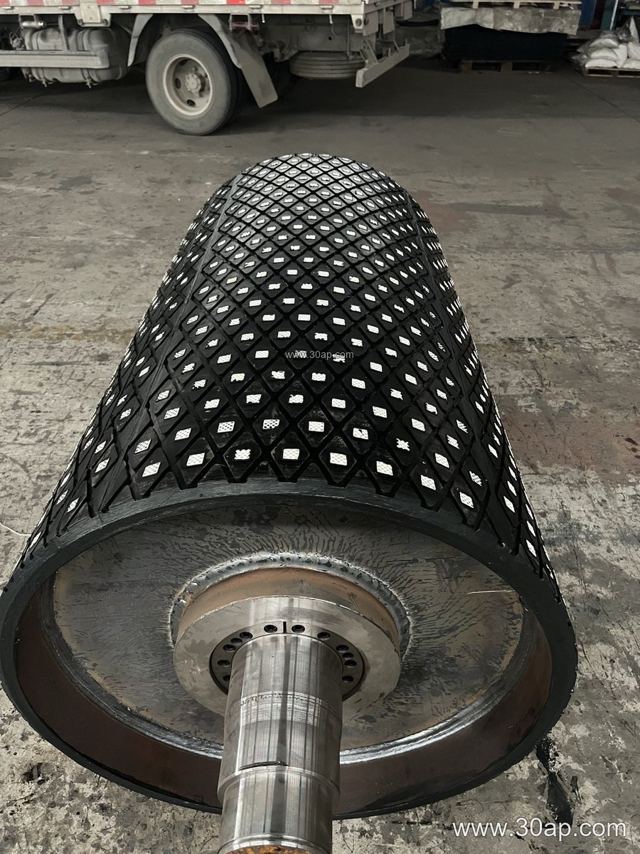
How a Pulley Is Built and Machined
Most heavy-duty pulleys start as a rolled steel shell welded to dished or flat end discs. The shaft is pressed or shrink-fitted into the hubs, then the whole assembly is machined in one setup where possible so that shell, hubs, and journals share a common centerline.
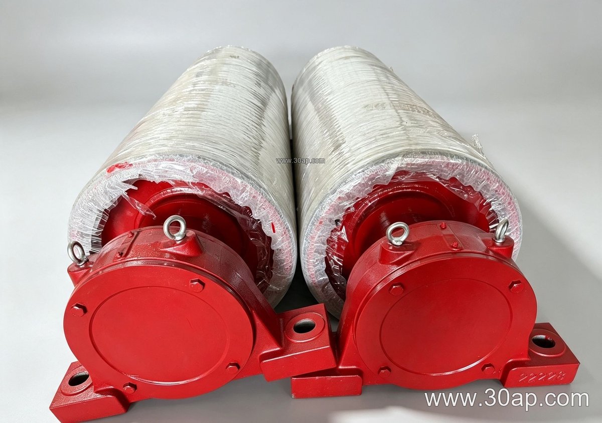
- Shell turning: the outer drum is machined to remove weld distortion and prepare the surface for lagging.
- Journal machining: shaft ends are turned and ground to fit bearing seats within the tolerance the bearing supplier specifies.
- End disc and hub work: faces are squared and bores bored to accept the shaft or bearing housing.
- Balancing: after machining and lagging, the pulley is checked for dynamic balance, especially at larger diameters.
The driven pulley, often called the drive pulley or head pulley, usually sees the highest torque, so its shaft and hub machining receives extra attention. Tail pulleys and bend pulleys handle lower loads but still need accurate journal work to keep the belt tracking through the return run.
Where Machined Pulleys Are Used
Machined conveyor pulleys appear wherever bulk material moves on a belt. In a limestone quarry, a drive pulley at the head end pulls the loaded belt up an incline. In a cement plant clinker circuit, bend pulleys route the belt around take-up sections. In a power station coal yard, tail pulleys at the loading point must resist fines and moisture while keeping the belt centered.
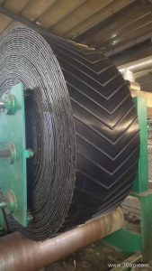
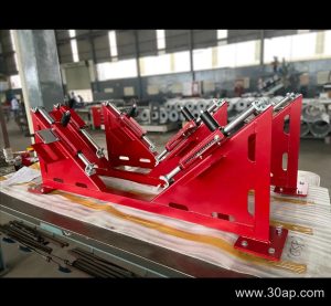
The pulley does not work alone. It interacts with the conveyor belt, the idler roller sets that support the belt, and the conveyor bracket that anchors the bearing housing to the frame. Good machining tolerances on the pulley help all three perform as intended.
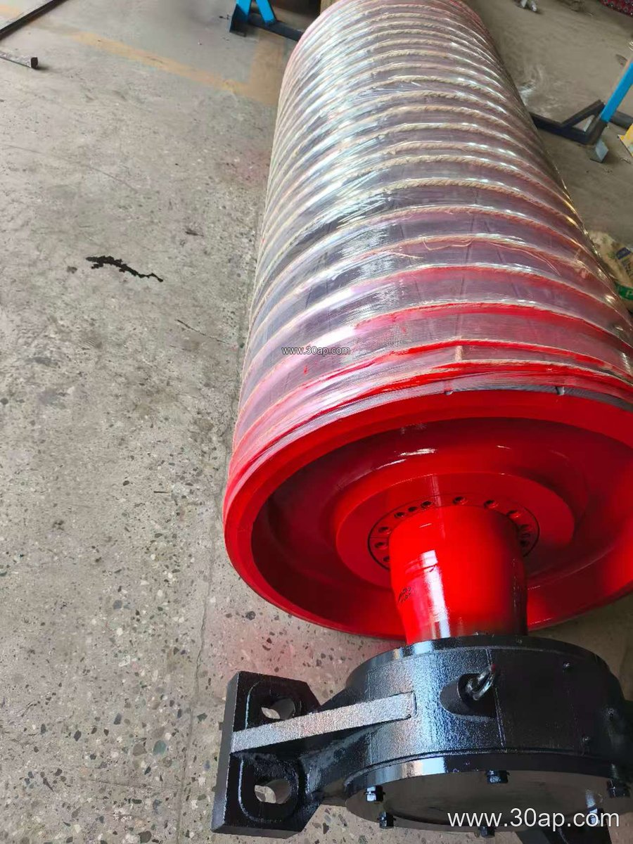
Common Reference Dimensions
The table below gives typical reference values used in specification discussions. Actual sizes are determined by the conveyor design, belt tension, and torque, not by belt width alone.
| Item | Common reference values |
|---|---|
| Belt width (B) | B400, B500, B650, B800, B1000, B1200, B1400, B1600 |
| Pulley diameter (Ø) | Ø200, Ø250, Ø315, Ø400, Ø500, Ø630, Ø800, Ø1000, Ø1250 |
| Shell face width | Usually wider than belt width, e.g. B800 about 950 mm, B1200 about 1400 mm |
| Shaft diameter | Ø50, Ø60, Ø70, Ø80, Ø90, Ø100, Ø120, Ø140, Ø160 |
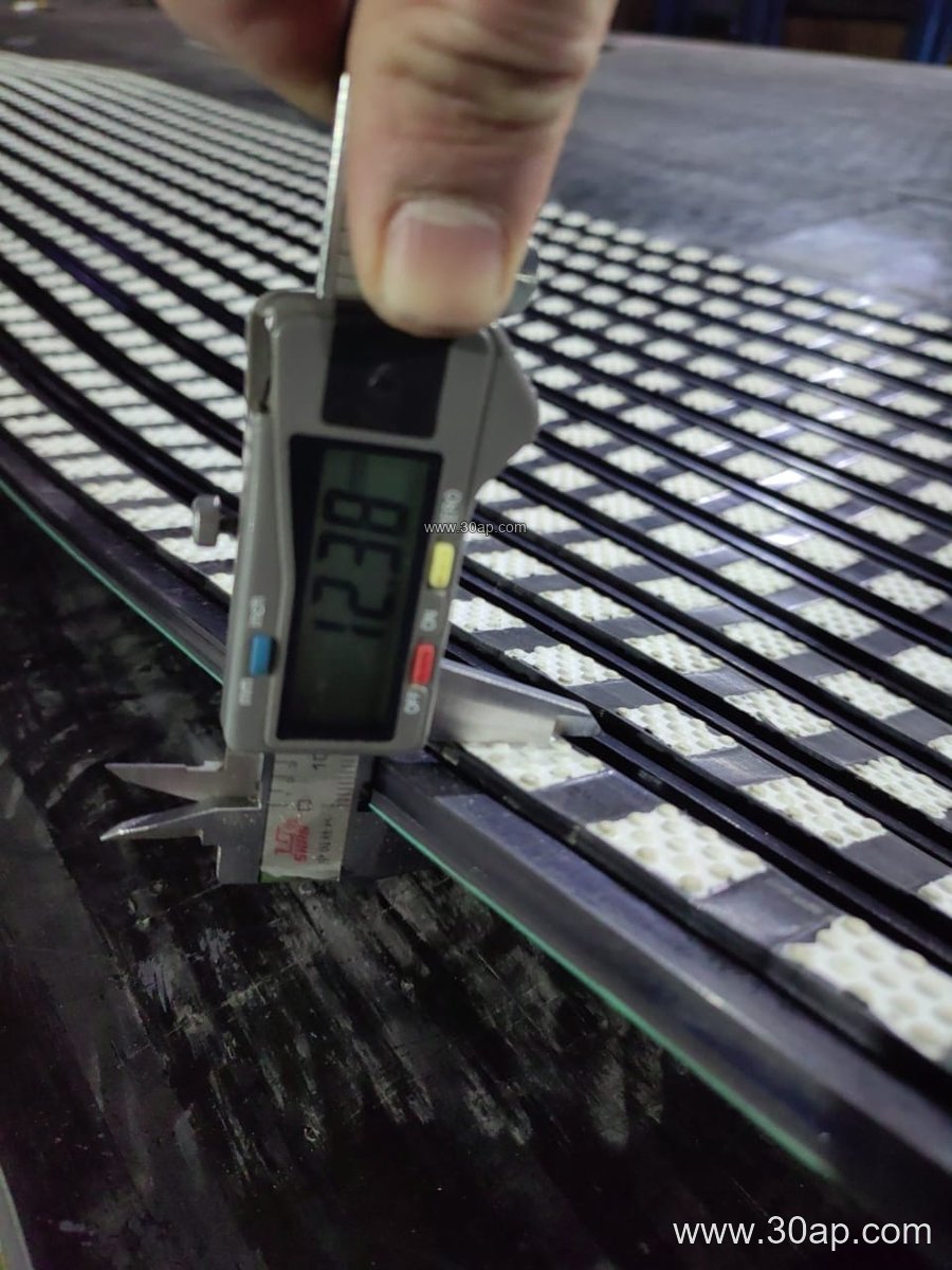
| Lagging thickness | 8, 10, 12, 15, 20 mm |
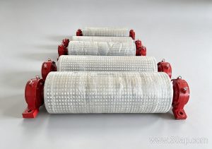
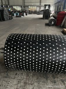
| Surface form | Plain, cold-bonded rubber, hot vulcanized rubber, diamond lagging, chevron lagging, ceramic lagging |
Combinations such as B800 × Ø500 or B1200 × Ø1000 are common starting points, but a B1200 belt may run on more than one diameter depending on wrap angle and tension. Shaft diameter follows torque and load calculations rather than a fixed rule from belt width.
What Buyers Should Check Before Ordering
When specifying conveyor pulley machining, buyers should confirm the shaft material and its heat treatment, the bearing seat tolerance, the lagging type and thickness, and the required balance grade. For a wash plant or a fertilizer handling line, corrosion protection on the machined surfaces may be as important as dimensional accuracy.
It also helps to state the pulley’s position in the conveyor, because a drive pulley, a tail pulley, and a bend pulley are not interchangeable. Each has different torque, wrap, and loading conditions, and the machining drawing should reflect that. A clear drawing with shell diameter, face width, shaft diameter, keyway size, and lagging specification prevents costly rework and keeps the belt conveyor running smoothly.