What an Integral Pulley Is and Why It Matters
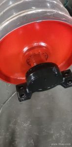
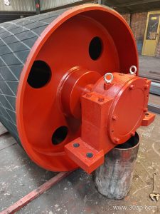
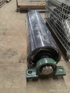
An integral pulley is a conveyor pulley whose shell, end discs, and shaft are manufactured as one continuous unit rather than assembled from separate welded or bolted components. In many industries—from a limestone quarry feeding a crushing circuit to a coal washing plant or a cement clinker line—this construction offers a stiff, concentric rotating body that keeps the conveyor belt tracking reliably under heavy loads. The term is sometimes written as an integral conveyor pulley, and it refers to the same product: a one-piece drum that drives, tensions, or redirects the belt.
It is important not to confuse an integral pulley with other drum positions. A drive pulley (also called the head pulley) transmits power to the belt, while a tail pulley sits at the opposite end and a bend pulley changes the belt’s direction. These are not interchangeable names. An integral pulley can serve in any of those roles, but the article here focuses on the integral construction itself, not on replacing drive, tail, or bend functions with one another.
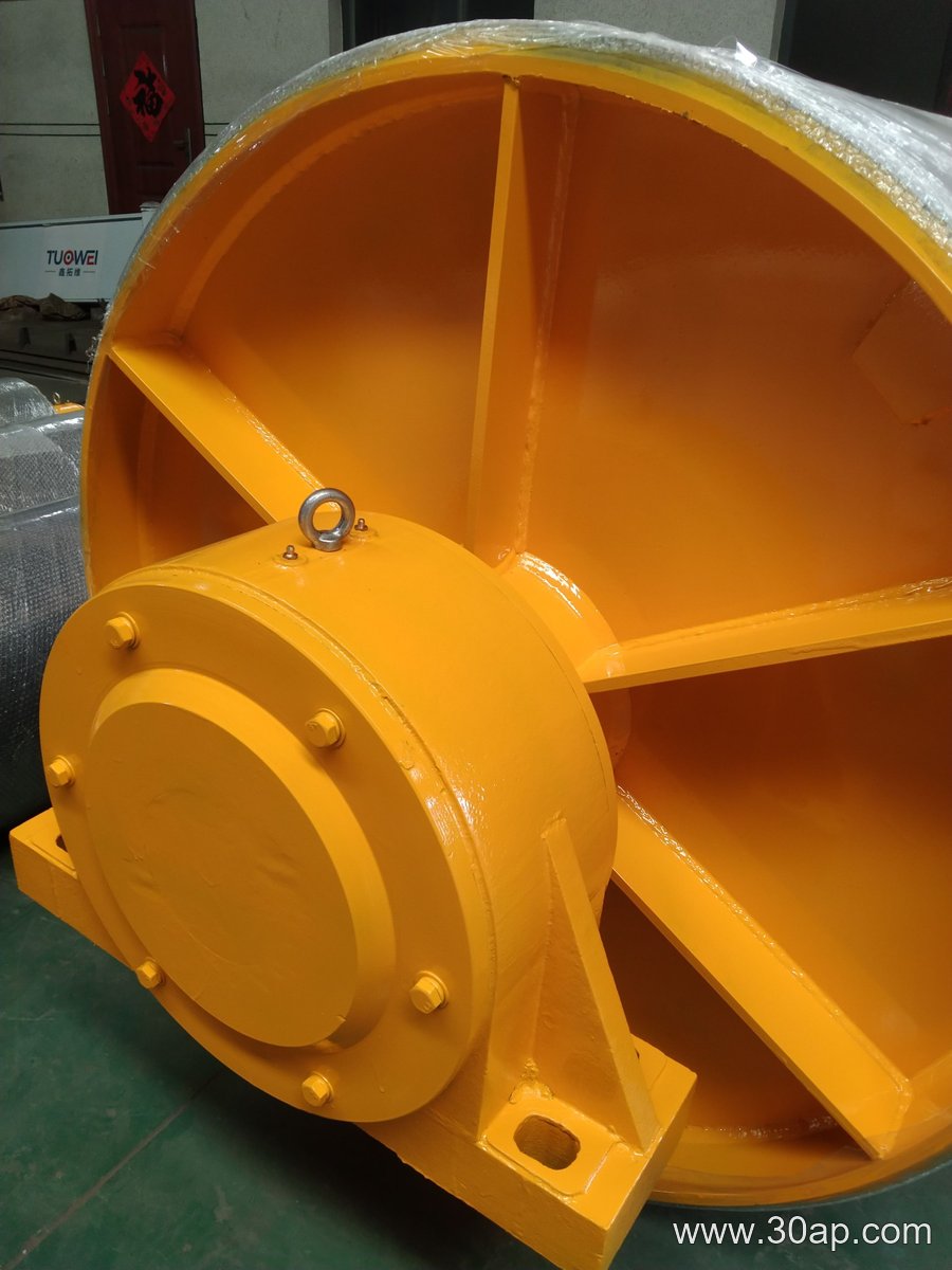
How an Integral Pulley Is Built
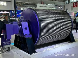
Manufacturing starts with a seamless or rolled steel shell, to which end discs are joined before the shaft is integrated. Depending on the design, the shaft may be friction-welded, cast-in, or machined as part of the hub assembly. The result is a single body with fewer joints, which reduces the risk of runout and vibration. Surface treatment follows: plain finish, cold-bonded rubber, hot-sulfur vulcanized rubber, diamond grooving, herringbone grooving, ceramic lagging, or flat rubber. Lagging thickness commonly ranges from 8 mm to 20 mm. A common example is a B1200 × Ø1000 integral pulley with 12 mm diamond lagging for a coal yard; another is B800 × Ø500 for a small aggregate transfer point. These are reference combinations, not fixed rules.
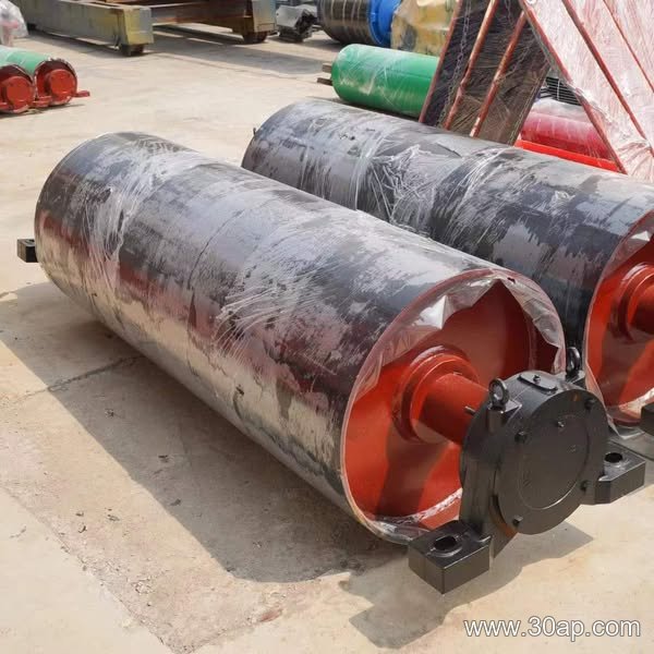
Where It Is Used
You will see integral pulleys in abrasive and high-torque settings such as iron ore terminals, copper concentrators, power plant coal handling, tunnel muck removal, and fertilizer or grain silo conveyors. A typical installation pairs the pulley with a conveyor belt, idler rollers, and a sturdy conveyor bracket. In a sand and gravel line, an integral tail pulley often operates in a wet, gritty environment where a welded drum might loosen over time. At a steel mill sinter plant, an integral bend pulley helps guide the belt around a transfer tower. The one-piece body resists fatigue better when the belt tension is high and the duty cycle is continuous.
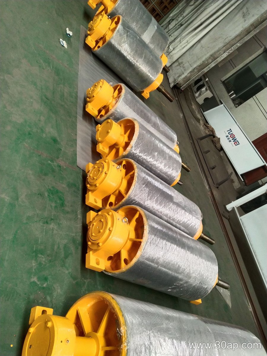
Key Parameters Buyers Should Check
When specifying an integral pulley, engineers usually work from belt width, required diameter, shaft load, and surface friction. Belt widths from B400 to B2400 are common. Diameters often range from Ø200 to Ø1800, though the right diameter depends on belt tension and wrap angle, not on width alone. The following table lists typical reference values.
| Belt width | Typical shell face width | Example diameter range | Common shaft diameter |
|---|---|---|---|
| B400 | approx. 500 mm | Ø200–Ø315 | Ø50–Ø60 |
| B650 | approx. 750 mm | Ø250–Ø400 | Ø60–Ø80 |
| B800 | approx. 950 mm | Ø315–Ø500 | Ø80–Ø100 |
| B1000 | approx. 1150 mm | Ø400–Ø630 | Ø100–Ø120 |
| B1200 | approx. 1400 mm | Ø500–Ø800 | Ø120–Ø140 |
| B1400 | approx. 1600 mm | Ø630–Ø1000 | Ø140–Ø160 |
| B1600 | approx. 1800 mm | Ø800–Ø1250 | Ø160–Ø180 |
Do not assume that a given belt width matches only one pulley diameter, and never derive a fixed shaft diameter from width alone. Shaft size is determined by torque and bending load, with common options including Ø50, Ø70, Ø90, Ø120, Ø160, and Ø200. Surface form should match the material: diamond or herringbone lagging for wet or slippery conditions, ceramic lagging for extreme abrasion, and plain or flat rubber for lighter duties.
Selection and Maintenance Notes
- Confirm the pulley’s role—drive, tail, bend, or take-up—so the integral body meets the correct load case.
- Check belt width against shell width, but allow for tracking clearance; for B1200, a shell face around 1400 mm is common.
- Choose lagging thickness based on slip risk and environment; 8–20 mm covers most needs.
- Inspect for cracks near the shaft-to-disc transition, especially in mines and quarries where shock loads occur.
- Keep the pulley aligned with idler rollers and conveyor brackets to avoid edge wear on the belt.
An integral pulley is not a universal answer for every conveyor, but in rugged service it offers a robust, low-vibration option. Work with your design data to match diameter, shaft, and surface to the actual duty, whether the conveyor moves clinker, coal, or crushed stone.