Calculating Bending Moments for an Eccentric Conveyor Bracket Design
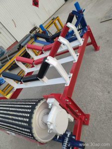
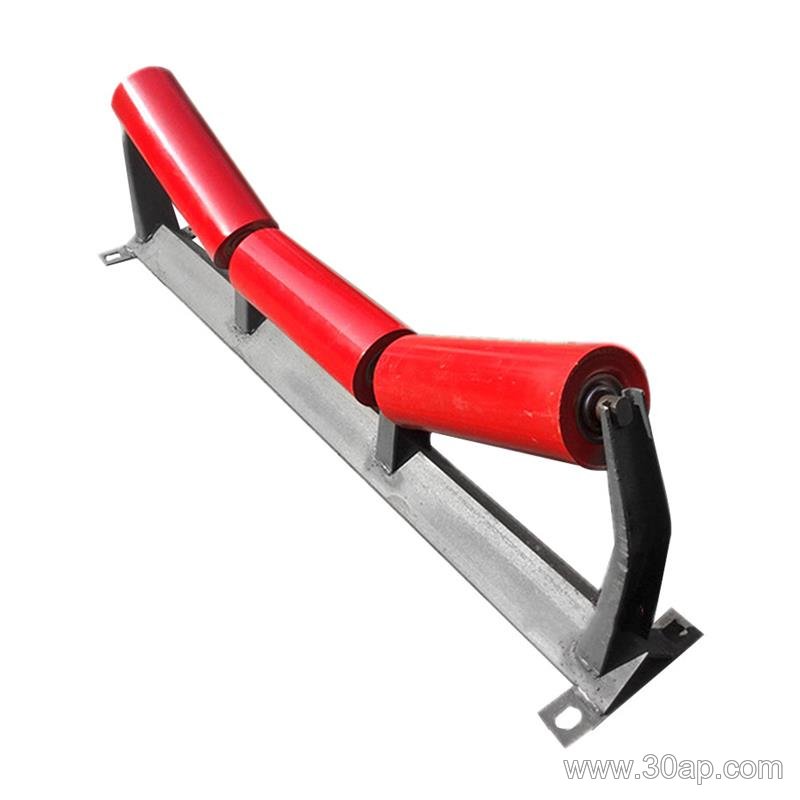
Designing a conveyor bracket requires rigorous structural analysis when asymmetrical bulk material handling creates off center loading forces. For this engineering example, we assume a hypothetical project involving a heavy duty conveyor bracket mounted on an exposed aggregate transfer line. Our primary design objective is to evaluate how eccentric vertical loads from marginal idler roll offsets generate complex bending moments that must be counteracted by the conveyor bracket geometry and mounting footprint.
Defining the Hypothetical Project Parameters and Assumptions
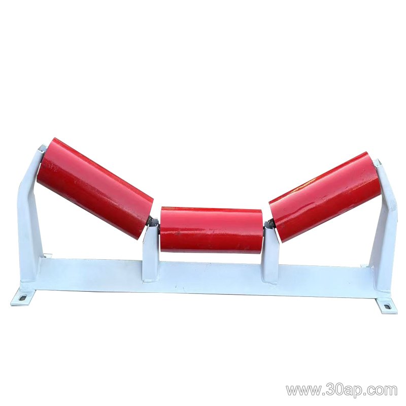
To establish a clear calculation method, we outline the baseline parameters for our hypothetical industrial layout. The conveyor bracket must support a troughing idler assembly carrying a continuous stream of crushed stone moving at moderate speeds.
- Idler dead weight acting through the center of gravity: $W_i = 450\,\text{N}$
- Maximum asymmetric material surcharge weight acting on one side: $W_m = 1200\,\text{N}$
- Effective moment arm distance from the stringer mounting face to the resultant vertical load vector: $e = 180\,\text{mm}$
- Material yield strength for structural carbon steel plate: $S_y = 250\,\text{MPa}$
- Assumed safety factor for dynamic bulk handling conditions: $SF = 2.0$
These values frame our engineering decisions regarding plate thickness, gusset placement, and bolt pattern spacing. Because the bulk material distribution fluctuates during normal plant operation, the conveyor bracket experiences cyclical torsional stress alongside standard flexural bending.
Mathematical Method for Bending Stress Determination
The core mechanical challenge in this layout stems from the eccentricity of the applied load. When a downward force acts at a horizontal distance from the primary support channel, it generates a direct bending moment ($M$). We calculate this moment using the standard engineering formula:
$$M = (W_i + W_m) \times e$$
Substituting our hypothetical project values into the equation gives:
$$M = (450\,\text{N} + 1200\,\text{N}) \times 0.180\,\text{m} = 16550\,\text{N}\cdot\text{mm} \text{ or } 279\,\text{N}\cdot\text{m}$$
Next, to determine the resulting bending stress ($\sigma_b$), the engineering team evaluates the cross sectional section modulus ($Z$) of the primary cantilever arm of the conveyor bracket. Assuming a rectangular plate cross section with a depth ($h$) of $120\,\text{mm}$ and a thickness ($b$) of $12\,\text{mm}$, the section modulus is calculated as:
$$Z = \frac{b \cdot h^2}{6}$$
$$Z = \frac{12 \cdot 120^2}{6} = 28800\,\text{mm}^3$$
Dividing the bending moment by the section modulus yields the maximum outer fiber stress experienced by the conveyor bracket:
$$\sigma_b = \frac{M}{Z} = \frac{279000\,\text{N}\cdot\text{mm}}{28800\,\text{mm}^3} \approx 9.69\,\text{MPa}$$
Translating Calculations Into Engineering Decisions
Our computed bending stress of $9.69\,\text{MPa}$ appears modest when compared directly against the $250\,\text{MPa}$ yield strength of standard structural steel. However, static calculations only tell part of the story. In real world material handling environments, impact shocks from large falling rocks and continuous motor vibration introduce fatigue multipliers. Therefore, our engineering decisions must account for dynamic amplification factors.
To safeguard the structural integrity of the conveyor bracket under these unpredictable load spikes, the design team introduces three specific modifications:
- Welding a triangular gusset plate into the interior 90 degree angle to drastically increase local section modulus and mitigate shear stress concentrations.
- Upgrading the fastener specification from standard grade bolts to high tensile fasteners, preventing joint separation under fluctuating torsional loads.
- Specifying continuous fillet welds along the primary load bearing joints rather than intermittent tack welds, ensuring uniform load transfer across the entire profile of the conveyor bracket.
Through this step by step hypothetical calculation and structural adjustment process, engineers ensure that the conveyor bracket maintains long term mechanical stability without over-engineering the assembly weight or driving up unnecessary material costs.