How to Install a Conveyor Pulley on a Wet Outdoor Conveyor
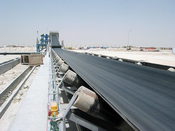
What does it take to install a conveyor pulley correctly on a wet outdoor conveyor? The answer lies in disciplined preparation, precise mounting, careful alignment, and thorough commissioning checks. Unlike indoor installations, wet outdoor conveyors expose the pulley to rain, humidity, and temperature swings, so each step must account for corrosion, slippage, and structural stress. The following guidance applies to most drum and wing conveyor pulleys used in such conditions.
Preparation Before Mounting
Begin by inspecting the conveyor pulley for shipping damage, verifying that the shaft diameter and keyway match the drive or bearing assembly, and confirming that the lagging (if present) is intact. For a wet outdoor conveyor, apply a corrosion-resistant coating to any exposed carbon steel surfaces and ensure that drain holes in the pulley end discs are clear. Prepare the mounting area: clean the shaft, check bearing housings for wear, and have shims, feeler gauges, a laser alignment tool, and a torque wrench on hand. If the conveyor is in a coastal or highly humid environment, consider stainless-steel fasteners to reduce galvanic corrosion.
Mounting and Alignment
Mount the conveyor pulley by first positioning it loosely on the bearing supports. For a wet outdoor conveyor, ensure that the pulley is slightly higher than the tail or head pulley to allow water runoff. Align the pulley shaft with the drive shaft using a laser or dial indicator. Acceptable misalignment is typically less than 0.05 mm per 100 mm of shaft length, but always follow the manufacturer’s specification. Check parallel and angular alignment in both horizontal and vertical planes. After alignment, tighten bearing bolts to the recommended torque and recheck alignment, as tightening can shift the pulley. Verify that the belt tracks centrally by rotating the pulley by hand.
Commissioning Checks
Before running the conveyor, confirm that all guards are in place and that the pulley rotates freely. Start the conveyor at low speed and observe belt tracking for the first few revolutions. In wet conditions, watch for water pooling on the pulley surface, which can cause belt slip; if slip occurs, adjust tension or consider a lagged pulley. Check bearing temperature after 30 minutes of operation—it should stabilize below the manufacturer’s limit. Listen for unusual noise and inspect for vibration. After the first hour, re-torque critical fasteners and recheck alignment. For outdoor installations, repeat these checks after the first rain event to ensure that moisture has not affected performance.
Conveyor Bracket Misalignment: A Single-Problem Troubleshooting Sequence
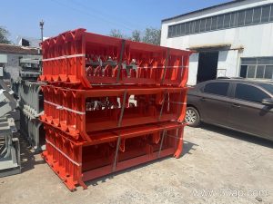
At a cement plant transfer point, a conveyor bracket that shifts out of alignment can cause the belt to track off-center, spill material, and accelerate wear on the idler frame. This article presents a focused troubleshooting sequence for that one operating problem. The sequence moves from immediate observation to root cause without replacing the bracket unnecessarily.
Step 1: Confirm the Symptom Is Bracket-Related
Before adjusting anything, verify that the misalignment originates at the conveyor bracket rather than at the belt, pulley, or loading chute. A bracket that has rotated or deflected will produce a consistent belt drift near that support. Inspect the bracket-to-stringer connection for elongation, cracked welds, or loose fasteners. If the bracket is visibly distorted or its mounting holes are ovalized, the problem is structural, not a simple adjustment.
Step 2: Check the Idler Frame and Roller Interface
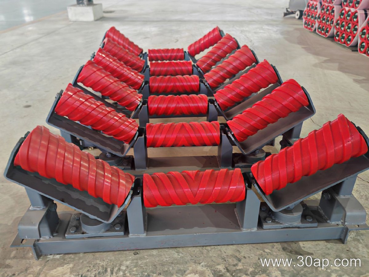
A conveyor bracket supports the belt conveyor idler frame, so any misalignment there can mimic a bracket fault. Measure the gap between the idler frame and the bracket seat. Uneven contact, a missing shim, or a bent frame will force the bracket to carry a side load. In a cement plant, dust buildup under the frame can also tilt the assembly. Clean the seat and recheck before condemning the bracket.
Step 3: Inspect for Thermal or Material Distortion
Clinker transfer points expose a conveyor bracket to radiant heat and abrasive dust. A Q355 conveyor bracket may resist deformation better than a lower-grade substitute, but no bracket is immune to thermal cycling. Look for a permanent twist or a bowed web. If the bracket has lost its original geometry, field straightening is rarely reliable; replacement with a bracket of the same grade and dimensions is the practical action.
Step 4: Verify Bolt Torque and Shim Stack
- Check that all bracket bolts are present and torqued to the project specification.
- Confirm the shim stack is uniform and not compressed unevenly.
- Look for paint or rust layers that can create a false seat.
If torque and shims are correct, the bracket itself is the likely cause. Mark the position, remove the bracket, and compare it against a known straight reference before ordering a replacement.
Step 5: Reassemble and Confirm Tracking
Install the new or repaired fixed conveyor bracket, align the idler frame, and run the belt empty. Observe the tracking for several minutes. If drift persists, the problem may be in the belt or loading condition, not the bracket. Document the final bracket position and bolt torque for future inspections.
Vulcanization and Carcass Construction: The Core of Conveyor Belt Quality
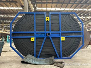
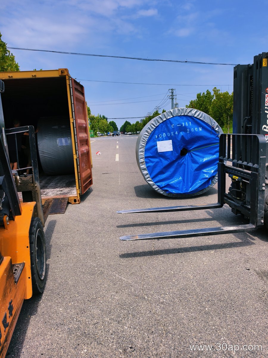
Many people assume a conveyor belt is simply a thick rubber band. In reality, it is a composite engineered product whose performance is determined by a series of precise manufacturing stages. Nowhere is this more evident than in a bulk-material port terminal, where a conveyor belt must handle sharp ores, heavy impact, and continuous operation. The manufacturing process—from fabric preparation to final vulcanization—directly influences how long the belt lasts and how reliably it performs.
Key Production Stages and Their Quality Effects
The manufacturing of a conveyor belt involves several critical steps. Each stage leaves a fingerprint on the finished product.
- Fabric and carcass preparation: Multiple plies of synthetic fabric (such as polyester-nylon) are woven and treated with adhesion promoters. The strength and number of plies determine the belt’s tensile strength and resistance to ripping. Poor impregnation can lead to ply separation under load.
- Calendering and rubber compounding: Uncured rubber is mixed with carbon black, sulfur, accelerators, and antioxidants. The compound is then calendered into thin sheets that are pressed onto the fabric. Inconsistent thickness or contaminated compound creates weak spots that crack prematurely.
- Building and shaping: The layered assembly is cut, spliced, and shaped into a continuous belt. Any misalignment or trapped air at this stage becomes a stress point during operation.
- Vulcanization: Heat and pressure cross-link the rubber molecules. Proper temperature and time ensure optimal elasticity and bond strength. Under-vulcanized belts soften and wear quickly; over-vulcanized belts become brittle and crack.
Why These Stages Matter at a Bulk Port Terminal
At a bulk port, a conveyor belt often moves iron ore, coal, or fertilizer under high impact and abrasive conditions. A belt with a well-constructed carcass resists impact tears, while a properly vulcanized cover resists gouging and wear. If the calendering stage left air pockets, the belt may delaminate when subjected to constant flexing over pulleys. If the vulcanization was uneven, the belt may harden in spots, leading to rapid failure. Thus, the manufacturing process is not an abstract factory detail—it is the foundation of reliable conveying.
Practical Takeaways for Specifiers
When selecting a conveyor belt for port terminal use, ask about the manufacturing controls rather than just the rubber type. Inquire how the carcass plies are bonded and whether the vulcanization is done under consistent pressure. These questions help ensure the belt you receive reflects the quality built into every stage.
Idler Roller Types: Impact vs. Trough in Mineral Processing
In a mineral-processing plant, an idler roller that handles sharp, heavy ore at the load zone faces different demands than one supporting the belt along the carrying run. Two common subtypes—impact idler rollers and trough idler rollers—are often compared for this duty. A common misconception is that any sturdy idler roller will do at the loading point. In reality, the mechanism of belt support changes the entire selection.
How Impact Idler Rollers Work
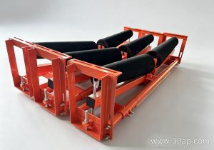
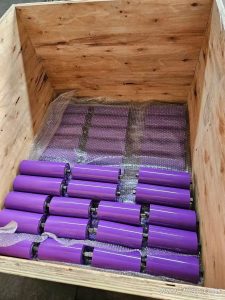
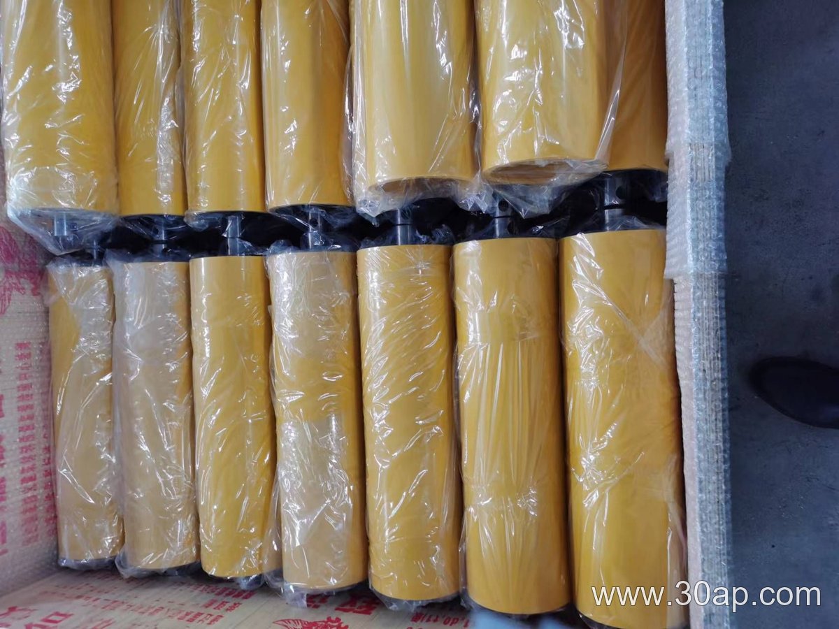
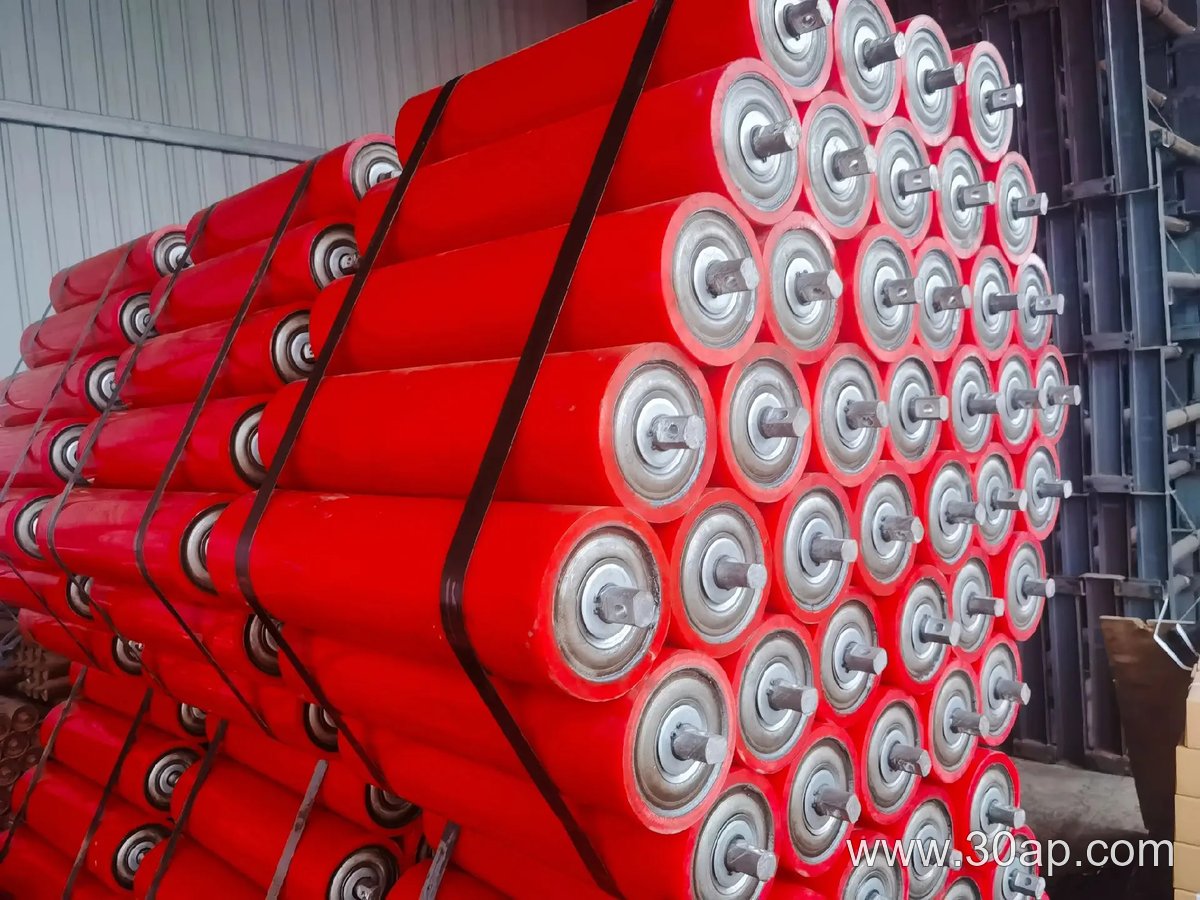
An impact idler roller uses a resilient, shock-absorbing surface—often rubber discs or a solid elastomer—to cushion the belt when ore drops onto it. The roller absorbs kinetic energy and reduces the chance of belt puncture or idler breakage. A trough idler roller, by contrast, is typically a steel or polymer cylinder arranged in a three-roll set that shapes the belt into a trough. It supports the load continuously along the run.
Benefits and Limitations
- Impact idler roller: Benefits include reduced impact damage and quieter operation. Limitations: higher cost, potential for material buildup between discs, and lower load capacity per roller. Suitable for transfer points with large lumps.
- Trough idler roller: Benefits include high load capacity, good belt tracking, and lower cost per unit. Limitations: poor shock absorption and risk of deformation from heavy direct impacts. Suitable for the carrying run after the load has settled.
When to Choose Each
In a hypothetical mineral-processing plant, an impact idler roller would be placed at the drop chute where ore falls from a crusher. A trough idler roller would follow on the main conveyor. For a conveyor carrying fine tailings with little impact, trough idler rollers alone may suffice. If the belt receives occasional large rocks, a hybrid approach—impact idlers at the load zone and trough idlers downstream—often gives the best balance of durability and cost.
FAQ
Can an impact idler roller replace a trough idler roller?
No. Impact idlers are designed for shock absorption, not continuous belt support. They typically have lower load ratings and should not be used as the primary carrying idler.
Do trough idler rollers require more maintenance?
They require inspection for bearing wear and alignment, but their simple construction often means fewer components to fail than impact idlers with rubber discs.
What about idler bearing selection?
Both subtypes rely on sealed bearings. For dusty mineral processing, choose bearings with good dust ingress protection. The impact idler roller may need a more robust bearing housing to survive vibration.