What This Work Covers
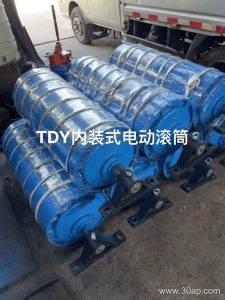
Conveyor pulley welding and machining is the stage where a rolled or spun shell, a shaft, and two end discs become a single load-bearing drum that can turn true under a tensioned belt. Welding joins the hub and disc assembly to the shell; machining brings the drum face, the shaft ends, and the bearing seats to the tolerances that keep a conveyor running straight. For a quarry or a cement plant, this is the difference between a pulley that runs quietly for years and one that shakes itself loose in a season.
This work applies to every position on a conveyor, but the demands differ. Drive pulleys transmit torque and see the highest belt tension, while a bend pulley only redirects the belt and carries far less load. Both are built and machined with the same basic steps, yet the inspection criteria are not identical.
How a Pulley Is Built Before Machining
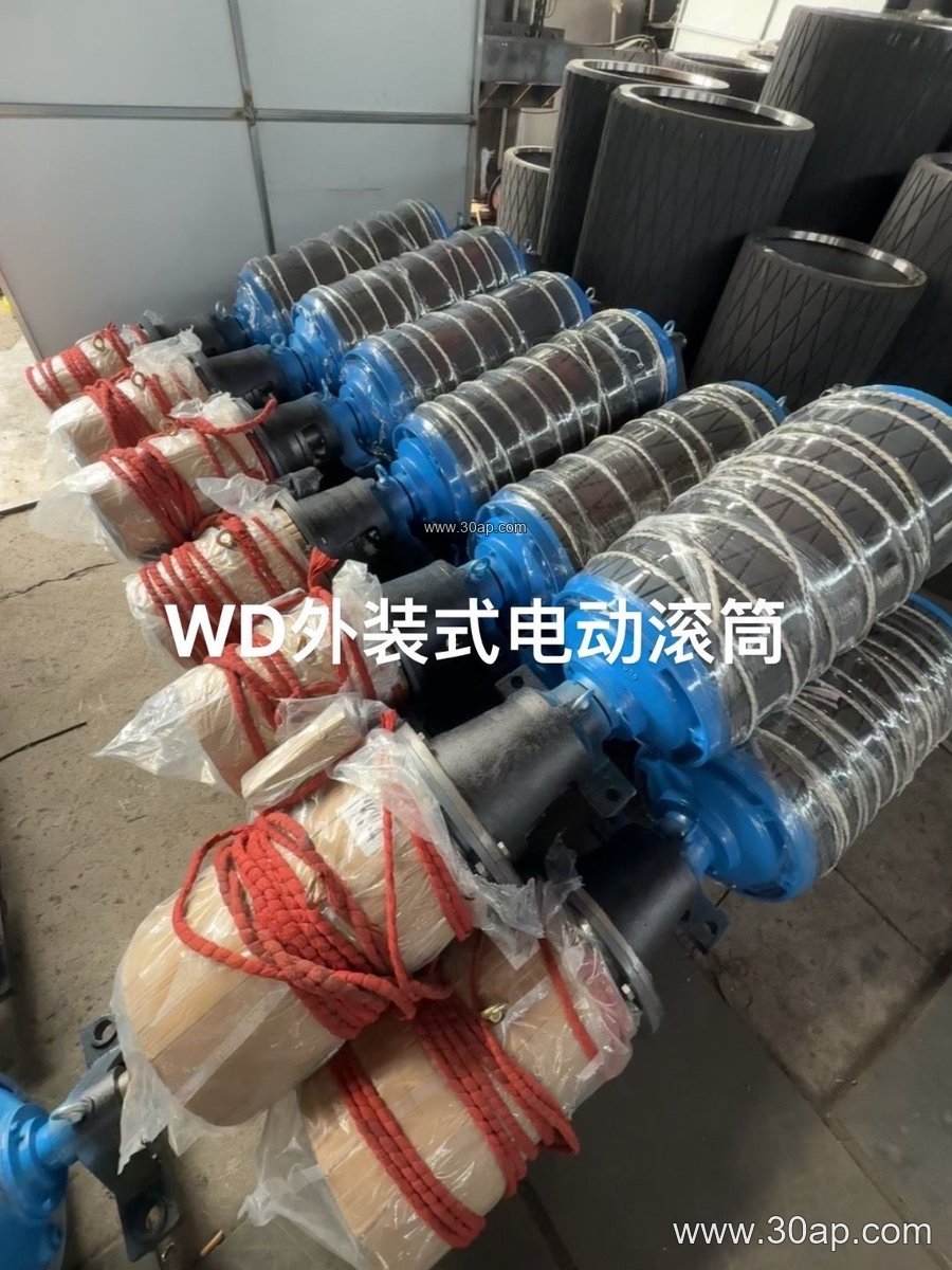
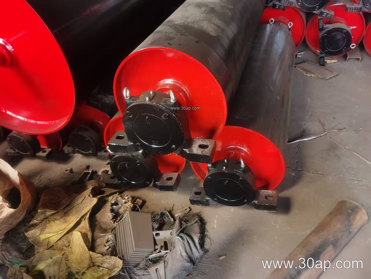
The shell usually starts as rolled steel plate or seamless tube. End discs are cut and bored for the shaft, then tacked in place. A hub is welded to each disc, and the shaft is pressed and keyed in. This is where welding quality matters most, because the disc-to-shell weld carries the belt tension into the shaft.
- Shell roundness checked before the discs go in
- Disc-to-shell fillet welds made on both sides where geometry allows
- Hub-to-disc welds sized to the torque of the drive duty
- Shaft alignment verified before final welding
Poor welding shows up later as runout, cracked welds at the disc, or a shaft that walks in the hub. A welder who works in a sequence that balances heat on both sides of the drum prevents most of this.
Machining Steps That Decide Running Quality
After welding, the drum goes to a lathe or a horizontal boring setup. The shaft ends are machined first, because they define the centreline. Then the bearing seats are turned to the required fit, and the drum face is machined to a clean cylinder. For a drive pulley, the face is often left slightly crowned or is machined flat and later covered with lagging.
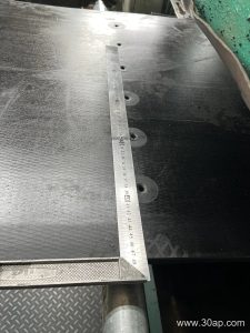
Key checks at this stage include shaft runout, bearing seat diameter and finish, face length, and the squareness of the drum face to the shaft. A pulley with a true shaft but a poorly machined face will still track badly, so both matter. Some workshops also balance the finished drum, especially for larger diameters where speed makes even a small imbalance noticeable.
Surface Preparation and Lagging
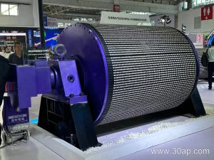
Many pulleys receive a rubber or ceramic covering after machining. The surface form is chosen for the duty rather than for appearance. A plain face suits a tail or bend position with low slip risk, while a drive pulley under heavy load often gets diamond or herringbone lagging to raise friction. Ceramic lagging is used where abrasive carry-back wears rubber quickly.
| Surface Form | Typical Use |
|---|---|
| Plain machined face | Bend, take-up, low-slip positions |
| Diamond rubber lagging | General drive pulleys |
| Herringbone lagging | Drive pulleys where belt wander is a concern |
| Ceramic lagging | Abrasive, wet, or high-torque drives |
Lagging thickness is commonly 8, 10, 12, 15, or 20 mm depending on the duty and the belt. The covering is bonded to a properly prepared shell, so machining quality before lagging still matters.
Matching the Pulley to the Belt Line
Belt width and pulley diameter are related but not locked together. A B800 belt might run on a Ø500 pulley at one station and a Ø800 pulley at another, depending on wrap angle, belt tension, and the space available. Face width is normally a little wider than the belt, for example B800 with roughly 950 mm face and B1200 with roughly 1400 mm face, but the exact figure comes from the conveyor design.
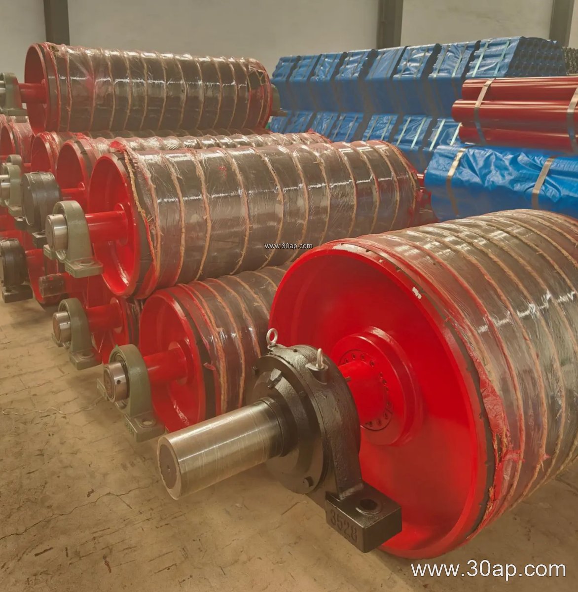
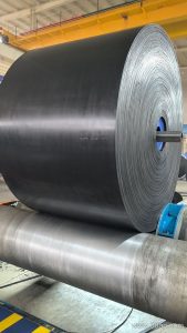
The belt itself influences the choice. A heavy-duty mining conveyor belt or a steel cord conveyor belt carries higher tension and needs larger shaft diameters than a light fabric belt. Shaft size is set by torque and bending load, not by belt width alone. A buyer should always supply the belt type, belt width, belt speed, and the pulley’s position, so the workshop can size the shaft correctly.
Where the Work Is Used
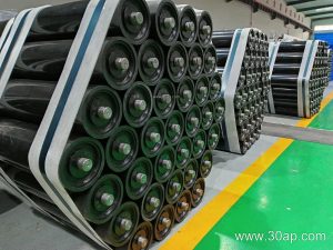
These drums appear across bulk handling. In a coal mining or underground mining conveyor, flame retardant conveyor belt and fire resistant conveyor belt are common, and the pulleys must be built to survive dusty, damp conditions. In a power plant coal yard, a abrasion resistant conveyor belt often runs over drive and bend pulleys that see constant grit. In aggregate and quarry lines, crusher conveyor belt and rock conveyor belt duties punish lagging, so ceramic or thick rubber covers are frequent.
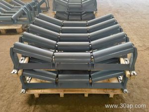
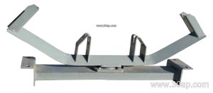
The same welding and machining standards apply in a cement plant, a port bulk terminal, or a steel plant sinter line. In each case, the pulley is one part of a system that includes the conveyor belt, conveyor pulley, idler roller, and conveyor bracket, and all of them need to line up.
What a Buyer Should Check
- Welding procedure and weld inspection records for disc and hub joints
- Machined shaft runout and bearing seat tolerance
- Face length and diameter against the conveyor drawing
- Lagging type and thickness suited to the material carried
- Balancing report for large or high-speed drums
- Paint, shaft protection, and lifting points for transport
Ask for the drawing that shows shaft diameter, face width, diameter, and lagging. A workshop that can explain why a given shaft size was chosen is usually a safer partner than one that quotes from a table alone.