What the Feed-End Pulley Does
The feed-end pulley is the conveyor pulley positioned at the loading end of a belt conveyor, where bulk material first lands on the belt. In many layouts this pulley also acts as the tail pulley, guiding the returning belt back into the carrying run. Its job is simple to describe but demanding in practice: support the belt at the point of impact, keep the belt tracking straight as it receives material, and transfer load smoothly into the conveyor frame. In a quarry, a limestone mine, or a crushing and screening line, this pulley often works in dust, grit, and constant shock loading, so the specification deserves more attention than it usually gets.
Because the belt arrives empty and leaves loaded, the feed-end pulley is exposed to a different stress pattern than a drive pulley or a bend pulley. It is not the component that transmits motor torque, and it should not be treated as a substitute for a drive pulley, a tail pulley in a different position, or a bend pulley on a return run. Each has its own role, and mixing them up leads to premature failure.
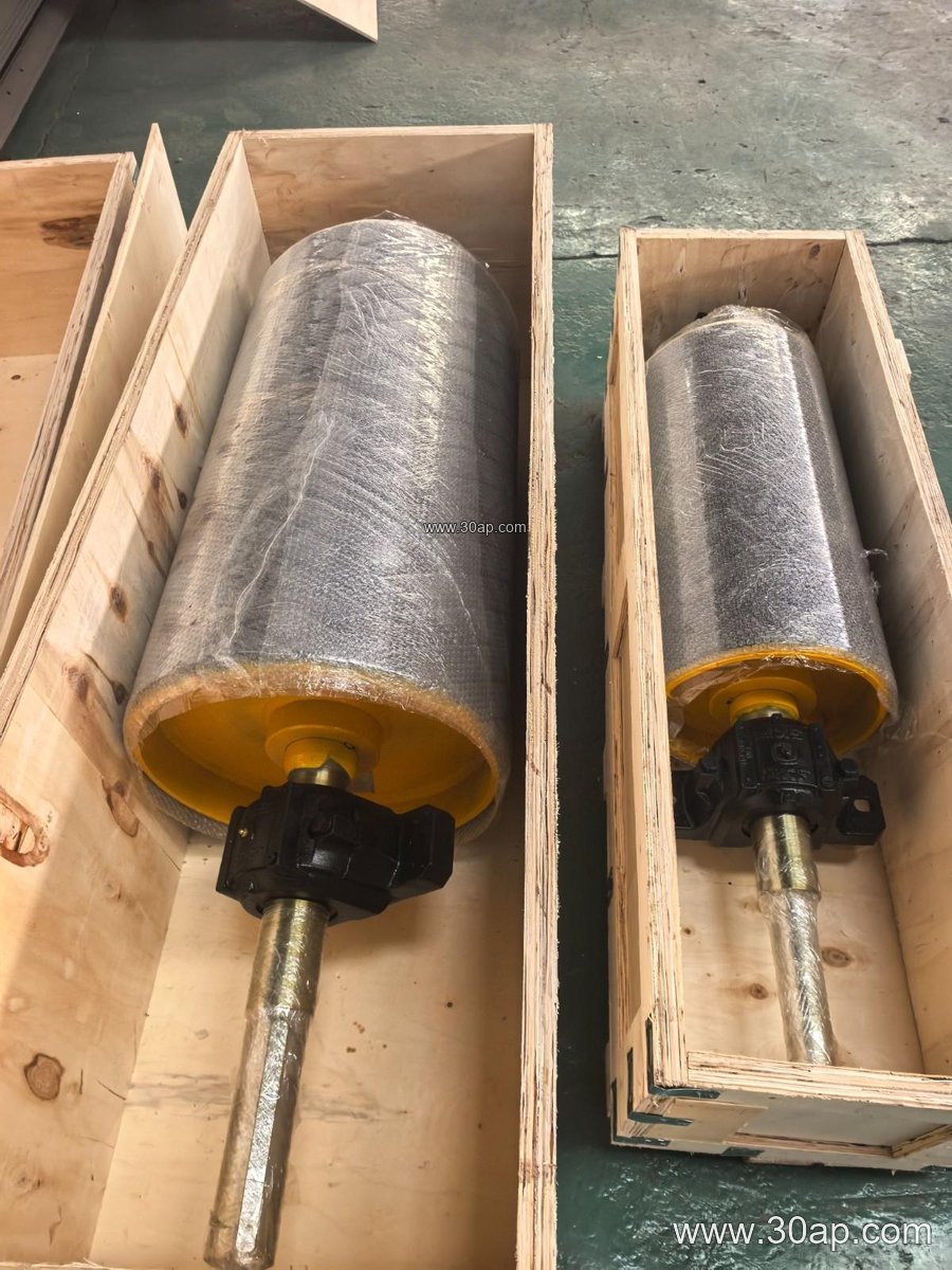
Construction and Surface Options
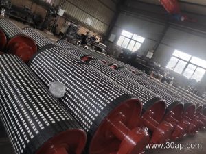
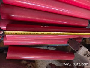
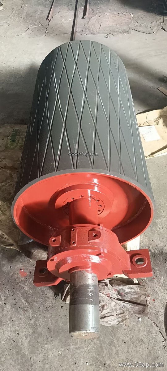
A typical feed-end pulley is built around a steel shell, welded to end discs and a shaft, with bearing housings mounted on a shaft or on a through-going axle. The shell is usually machined to control runout, and the surface may be plain or covered with rubber. Common surface forms include plain finish, hot-vulcanized rubber, cold-bonded rubber, diamond grooving, chevron grooving, and ceramic lagging. Lagging thickness is often 8, 10, 12, 15, or 20 mm, selected according to belt speed, material abrasiveness, and whether the pulley needs extra grip to prevent slip at start-up.
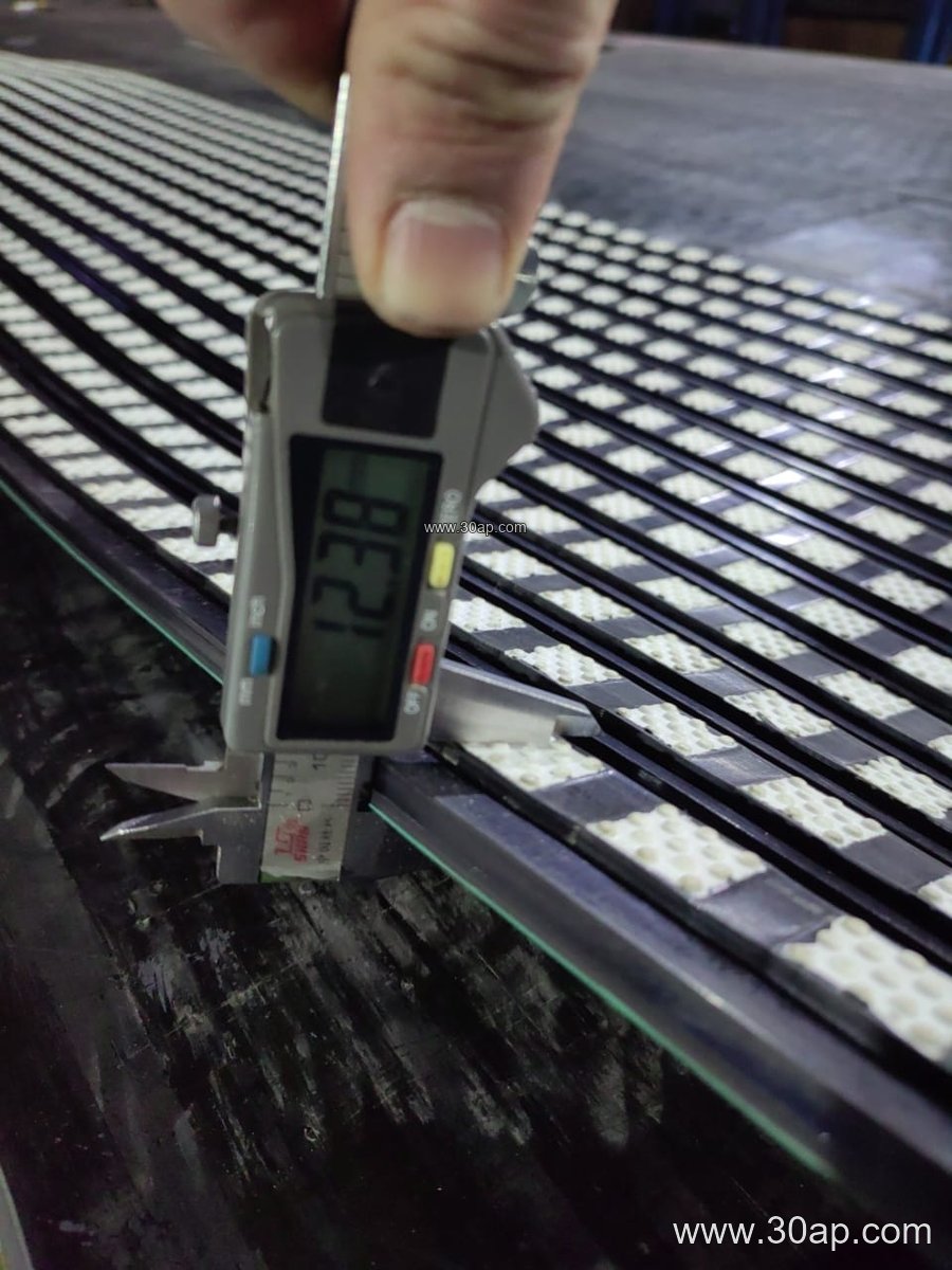
For a feed point handling abrasive rock from a crusher, a rubber-lagged shell protects both the pulley face and the belt. Where fines and moisture cause slip, a grooved or ceramic surface can improve traction. The pulley should be matched to the belt width and the conveyor frame, with the shell face typically slightly wider than the belt; for example, a B800 belt commonly runs on a pulley face of roughly 950 mm, and a B1200 belt on about 1400 mm. These are reference proportions, not fixed rules, and the final face width follows the conveyor design.
Where It Fits in the Plant
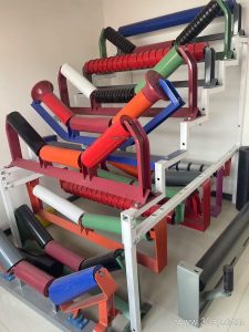
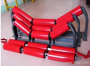
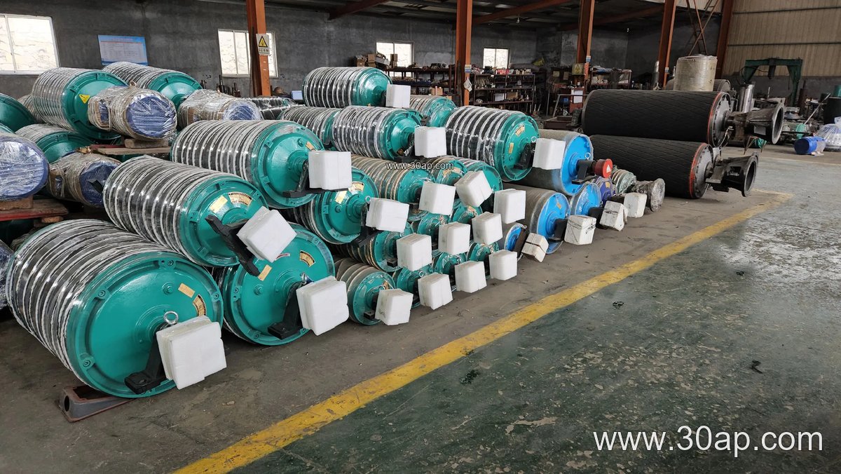
You will find the feed-end pulley at the start of a conveyor in a limestone quarry, an iron ore transfer station, a coal washing plant, a cement clinker line, or a power plant coal yard. It sits under the loading chute, often behind impact idlers and skirt boards, and it works with the conveyor belt, idler roller sets, and conveyor bracket assemblies to keep material centered. In a sand and aggregate plant, the same pulley may receive material from a screen or a crusher discharge, which means repeated impact and a high chance of spillage if the chute and skirt rubber are not aligned properly.
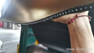
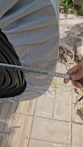
In heavier duty circuits, such as an ore conveyor or a bulk material conveyor handling wet and sticky feed, the pulley should be specified together with the belt. A heavy-duty mining conveyor belt, an abrasion resistant conveyor belt, or a flame retardant conveyor belt for underground coal mining all impose different demands on the pulley face. A steel cord conveyor belt and a multi-ply fabric core conveyor belt also differ in stiffness, so the pulley diameter and lagging pattern should be reviewed against the belt construction rather than chosen from a single catalogue page.
Common Size References
The table below shows representative combinations used in planning. Diameters and shaft sizes are determined by belt tension, torque, and load, not by belt width alone.
| Belt width | Typical pulley face | Common diameter range | Typical shaft range |
|---|---|---|---|
| B500 | about 600 mm | Ø250 to Ø400 | Ø50 to Ø80 |
| B650 | about 750 mm | Ø315 to Ø500 | Ø60 to Ø100 |
| B800 | about 950 mm | Ø400 to Ø630 | Ø70 to Ø120 |
| B1000 | about 1150 mm | Ø500 to Ø800 | Ø80 to Ø140 |
| B1200 | about 1400 mm | Ø630 to Ø1000 | Ø90 to Ø160 |
| B1400 | about 1600 mm | Ø800 to Ø1250 | Ø100 to Ø180 |
| B1600 | about 1800 mm | Ø1000 to Ø1400 | Ø120 to Ø200 |
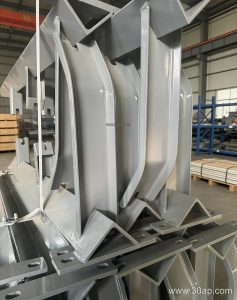
Combinations such as B800 × Ø500 or B1200 × Ø1000 are common in practice, but a B1200 belt is not limited to one diameter. Shaft diameter should be confirmed from the torque and bearing load calculation, and the bearing housing, locking assembly, and conveyor bracket must be checked together.
Buyer Checklist
- Confirm the pulley position and duty: feed point, tail position, or both, and state the belt width and belt type.
- Specify the lagging form and thickness, such as 10 mm diamond rubber or 15 mm ceramic, based on material abrasiveness and slip risk.
- Provide the belt tension and load data so the shaft, bearings, and shell thickness can be sized correctly.
- Check that the pulley face, chute, skirt rubber, and impact idler roller arrangement work together to center the belt.
- Ask for the balancing grade, runout tolerance, and bearing type in writing, since these affect vibration and service life.
For a conveyor carrying abrasive aggregate, a rubber-lagged feed-end pulley with a properly sized shaft is usually a sound starting point. For hot clinker or wet coal, the lagging compound and the belt cover grade should be reviewed together. More reference information on conveyor pulleys and matching belts is available at conveyor pulley and conveyor belt resources, while pulley and belt selection for mining duty can be discussed with the supplier using the site’s mining conveyor belt guidance.