Optimizing Trough Angle Selection for Industrial Conveyor Systems
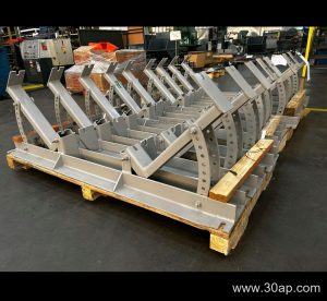
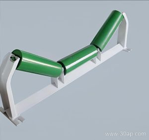
In heavy-duty aggregate and mineral processing applications, the geometric configuration of a bulk material handling line directly impacts operational efficiency. A core component in shaping this geometry is the Trough Idler Bracket, which supports the carrying idler roller assembly to form the belt into a concave shape. Properly aligning this assembly ensures that the rubber conveyor belt maintains its load-bearing profile without premature edge wear or excessive friction against the framework.
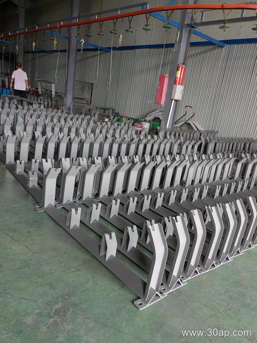
Engineers working on stone crushing systems and limestone operations must carefully evaluate the designated trough angle before final installation. Selecting an appropriate angle allows the system to maximize volumetric capacity while maintaining structural integrity across various operating speeds.
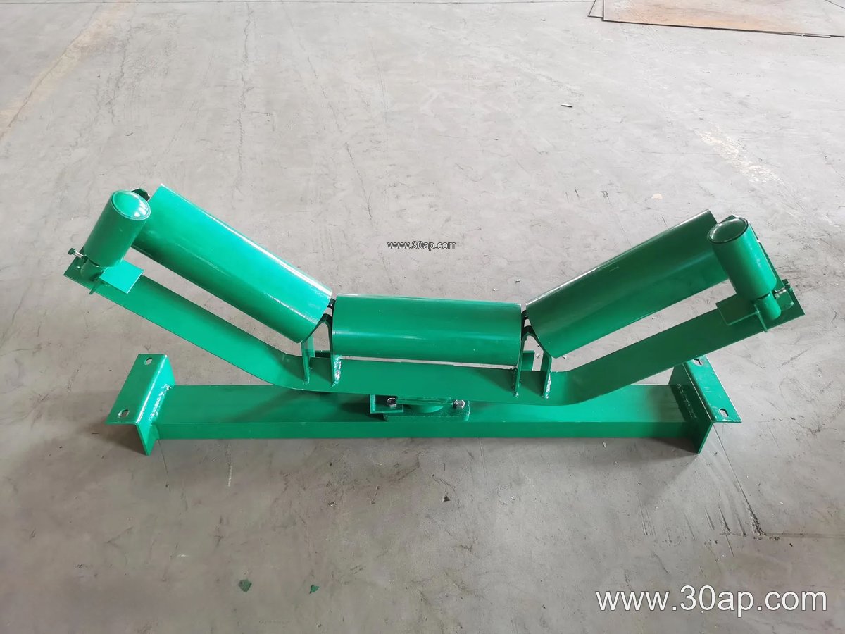
Technical Parameters and Dimensional Reference
Conveyor bracket configurations vary depending on the structural framework, load demands, and overall belt specification. Below is a reference table outlining typical engineering parameters used in heavy material transfer lines:
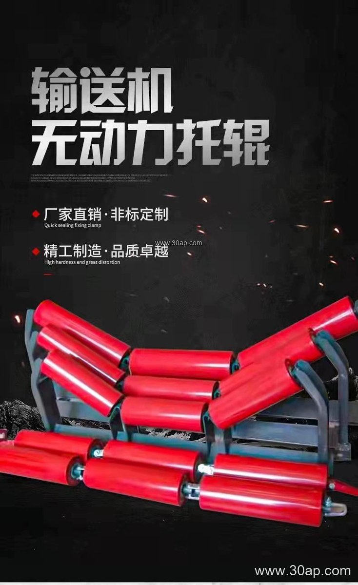
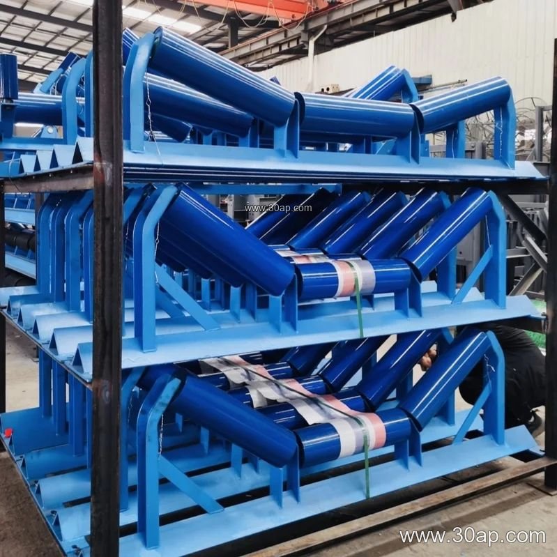
| Bandwidth Option | Supported Trough Angles | Common Roller Diameters | Primary Structural Material |
|---|---|---|---|
| B650 | 20 deg, 30 deg | Ø89, Ø108 | Steel Plate Bending / Channel Steel |
| B800 | 30 deg, 35 deg | Ø108, Ø133 | Angle Steel / Channel Steel |
| B1000 | 35 deg, 45 deg | Ø133, Ø159 | Structural Steel Plate |
| B1200 | 35 deg, 45 deg | Ø159, Ø194 | Heavy-Duty Steel Profile |
These values represent common design benchmarks rather than universal mandates. Actual installation hole spacing and crossbeam lengths adapt dynamically to site engineering requirements.
Integration with Belts and Rollers
The interaction between the Trough Idler Bracket, the idler roller, and the steel cord conveyor belt dictates the overall mechanical performance of the line. When materials are fed onto the belt from a primary crusher or transfer point, the bracket must absorb localized impact forces without shifting its alignment. Fixed variants provide rigid support in standard straight sections, whereas adjustable units allow technicians to fine-tune the inclination to prevent belt mistracking.
Furthermore, maintaining proper clearance around the drive pulley and tail pulley prevents material accumulation and reduces strain on the rotating elements. Routine inspections of the mounting bolts and structural welds ensure long-term reliability in demanding environments.