What an Ore Conveyor Pulley Does on a Bulk Handling Line
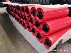
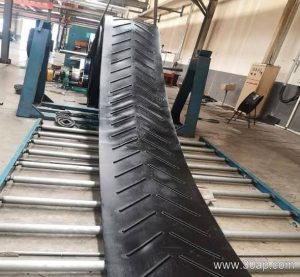
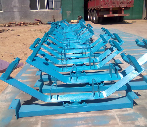
An ore conveyor pulley is the rotating drum that drives, tensions, or redirects the belt on a bulk material conveyor. In a crushing circuit, a sinter plant, or a port stockyard, this component carries the full belt tension and the weight of the material, so its construction and surface treatment matter as much as the belt itself. The pulley is usually matched to an ore conveyor belt and supported by conveyor brackets and idler rollers along the run.
On a typical line, the drive pulley transmits torque from the gearbox to the belt through friction between the shell surface and the belt cover. A tail pulley at the loading end sets belt tension, while bend pulleys route the belt through take-up systems. These are distinct roles: a drive pulley is not a tail pulley, and a bend pulley is not a replacement for either. The ore conveyor pulley discussed here is the general-purpose drum used across these positions, with the design adapted to each duty.
How the Drum Is Built
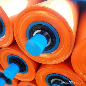
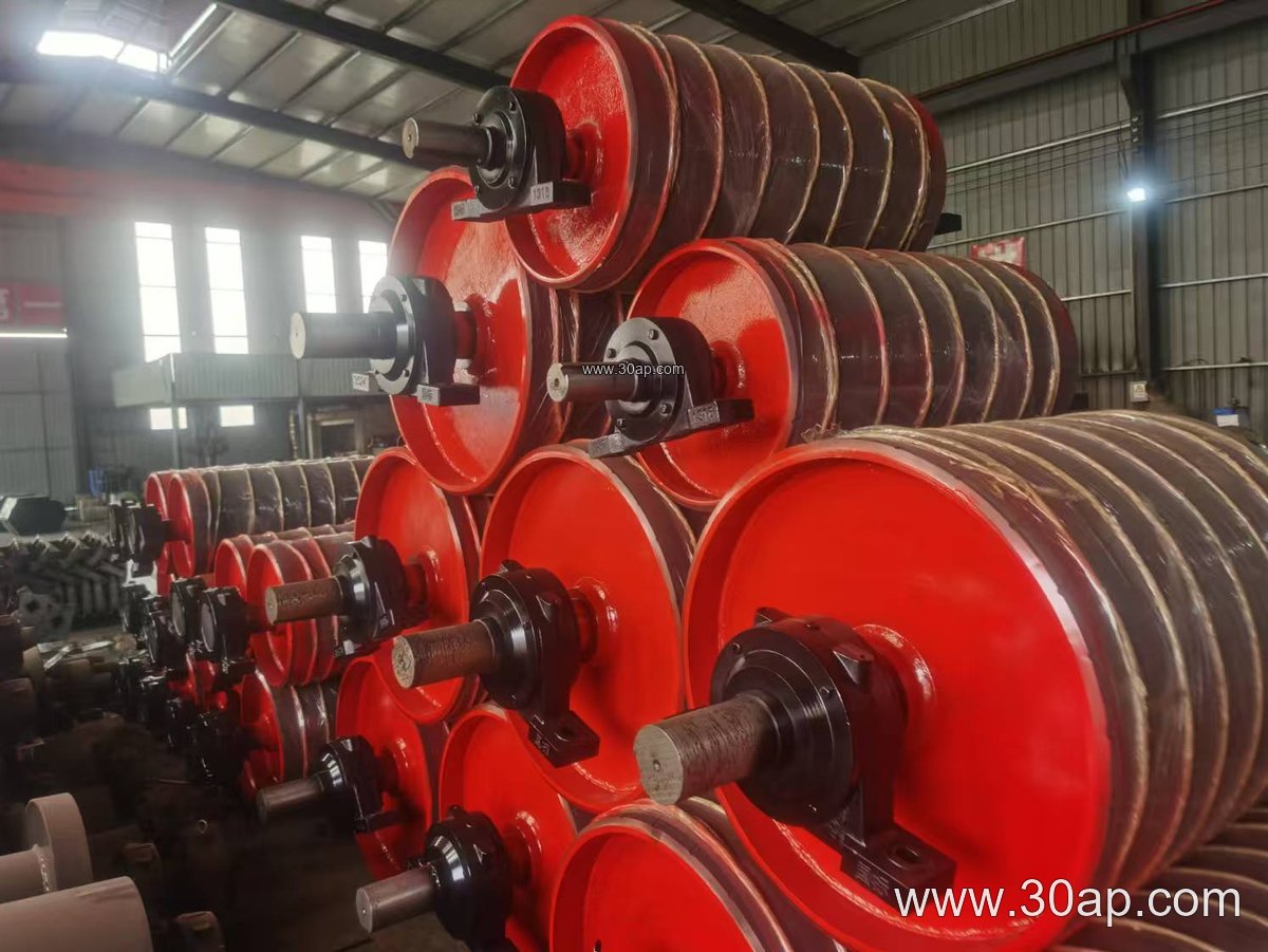
Most industrial drums use a welded steel shell with machined end discs and a through shaft. The shaft is sized by torque and radial load, not by belt width alone, so a B800 conveyor might use a Ø80 shaft in one layout and a larger shaft in another. Common shaft diameters include Ø50, Ø60, Ø70, Ø80, Ø90, Ø100, Ø120, Ø140, Ø160, Ø180, and Ø200. Shell diameters commonly range from Ø200 up to Ø1800 depending on tension and belt thickness.
The shell face is usually wider than the belt to allow for mistracking. For example, a B400 belt is often paired with a face around 500 mm, B800 with about 950 mm, and B1200 with roughly 1400 mm. These are typical proportions, not fixed rules, and the final face width is set by the conveyor designer.
- Shell: rolled and welded steel, machined for concentricity
- End discs: welded or shrink-fitted, with keyed or clamped shaft connection
- Shaft: carbon steel, sized by torque and load
- Bearing housings: bolted to the conveyor bracket
- Surface: plain, rubber lagged, or ceramic lagged
Surface Options and Grip
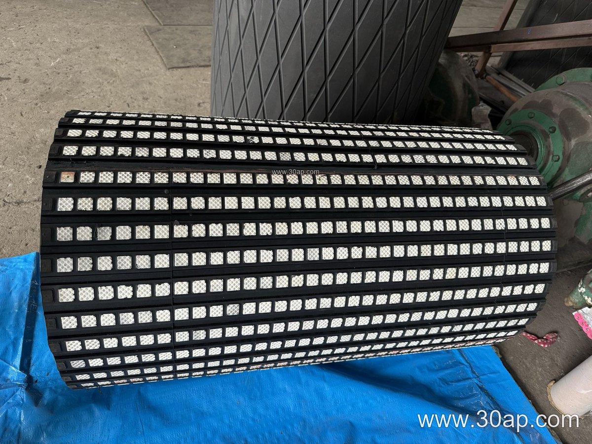
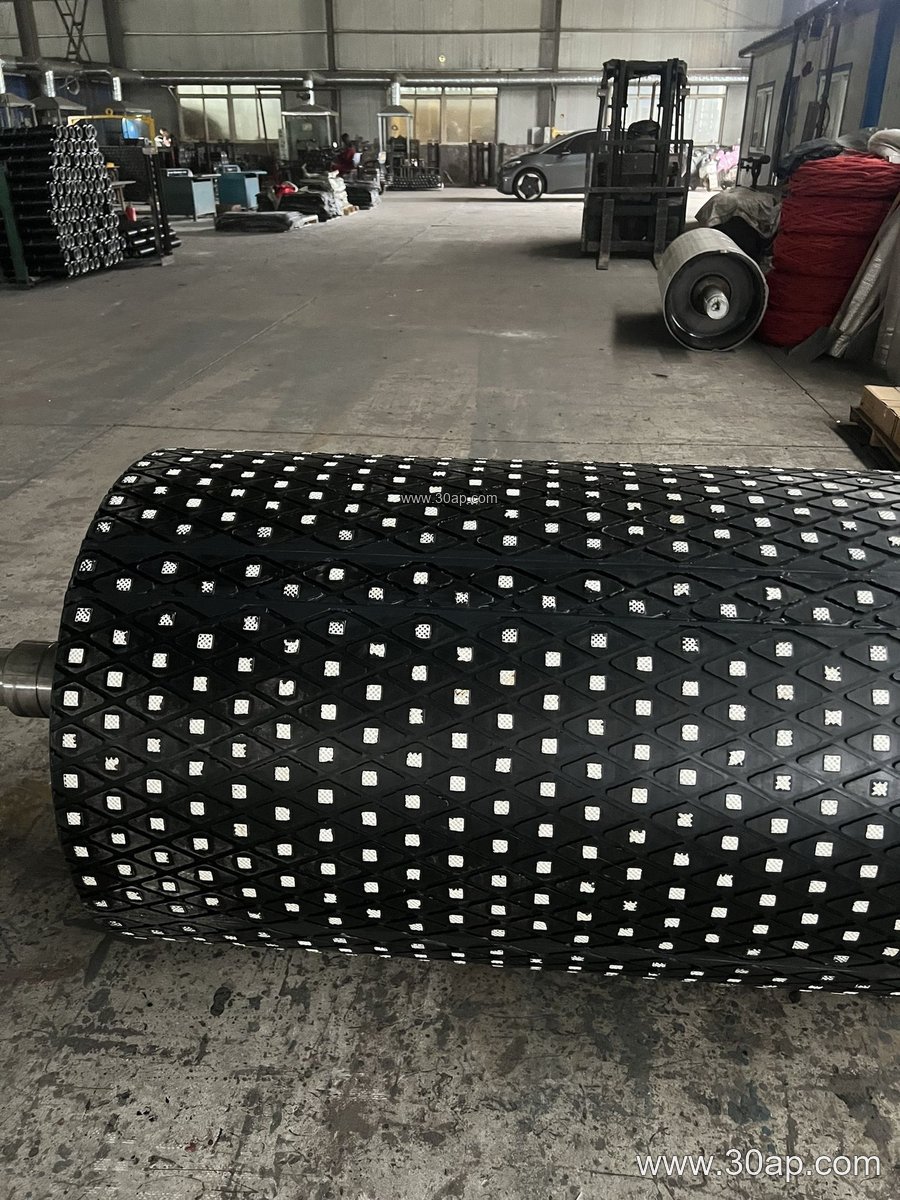
Lagging is the rubber or ceramic layer bonded to the shell to raise friction and protect the drum. Plain shells are common on bend and tail positions, while drive pulleys often use cast rubber, cold-bonded rubber, hot-vulcanized rubber, diamond groove, herringbone, or ceramic lagging. Lagging thickness commonly falls between 8 mm and 20 mm.
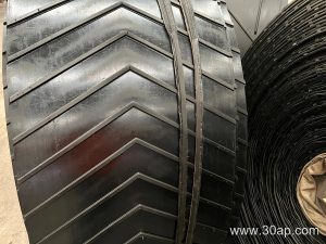
On a high-tension drive, diamond or herringbone lagging helps shed water and fines so the belt does not slip. Ceramic lagging is chosen where abrasive ore and wet conditions shorten rubber life. The belt cover should be considered together with the lagging: an abrasion resistant conveyor belt on the carrying side and a suitable pulley surface on the drive side give the best combination.
Matching the Pulley to Belt and Duty
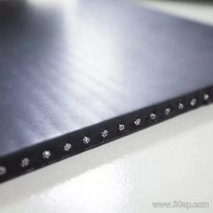
Belt construction influences pulley choice. A heavy steel cord conveyor belt needs a large-diameter drum to keep bending stress low, while a fabric-cored belt can run over a smaller drum. Common combinations include B800 × Ø500, B1200 × Ø1000, and B1400 × Ø800, but no single belt width locks the pulley to one diameter.
| Belt width | Typical pulley face | Common drum diameter range |
|---|---|---|
| B500 | about 600 mm | Ø250 to Ø500 |
| B650 | about 750 mm | Ø315 to Ø630 |
| B800 | about 950 mm | Ø400 to Ø800 |
| B1000 | about 1150 mm | Ø500 to Ø1000 |
| B1200 | about 1400 mm | Ø630 to Ø1250 |
| B1400 | about 1600 mm | Ø800 to Ø1400 |
| B1600 | about 1800 mm | Ø1000 to Ø1600 |
In a coal preparation plant or a power station coal yard, a flame retardant conveyor belt is often specified, and the pulley lagging should be selected to suit the same environment. In a quarry or aggregate line, a rugged quarry conveyor belt paired with a ceramic-lagged drive drum reduces slip and wear.
Installation and Maintenance Points
Alignment is the first check after installation. A misaligned ore conveyor pulley causes edge wear on the belt and premature bearing failure. Check that the drum axis is square to the conveyor centerline and that the bearing housings sit flat on the conveyor bracket. Confirm that the lagging is undamaged and that the belt tracks centrally on the shell face.
During operation, watch for slipping on the drive pulley, which usually indicates insufficient tension or worn lagging. Inspect the shell for cracks near the end discs, and check bearing temperature at regular intervals. Re-lagging is often cheaper than replacing a complete drum, provided the shell and shaft remain sound. Keep spare lagging sheets and fasteners on hand for critical lines in mines, cement plants, and ports.
Buyer Checklist
- Confirm the pulley position: drive, tail, bend, or take-up
- State belt width, belt type, and belt tension so the shell and shaft can be sized
- Choose the lagging pattern and thickness for the material and moisture level
- Specify shaft diameter from torque and load, not from belt width alone
- Check face width and bearing span against the conveyor frame
- Agree on inspection and documentation before shipment
Used alongside quality idler rollers and a well-matched mining conveyor belt, a correctly specified ore conveyor pulley keeps a bulk handling line running with fewer stoppages and less belt damage.