What the Impact Idler Bracket Does
An impact idler bracket is the support frame that holds the impact rollers directly beneath the loading point of a conveyor belt. Where a standard carrying bracket simply holds the belt in a trough, this bracket carries the extra vertical force produced when ore, coal, crushed stone or clinker drops onto the belt. In a quarry, a coal preparation plant or a cement plant, the loading chute is the place where the belt takes the hardest hit, and the impact idler bracket is the part that absorbs that energy before it reaches the frame and the belt cover.
Because the bracket sits in the load zone rather than along the normal carrying run, it is usually designed as a short, heavy section placed between the first standard troughing brackets. It is a bracket, not a roller, and it should not be confused with the troughing bracket used along the main run, nor with return brackets under the belt. Those brackets have different duties and different geometry.
How the Bracket Is Built
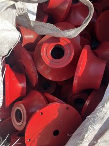
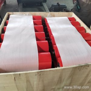
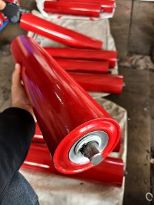
Most impact idler brackets are fabricated from angle steel, channel steel or folded steel plate, welded into a rigid frame with mounting pads for the rollers. The frame is often shorter and stiffer than a normal carrying bracket, because the impact zone needs to resist vibration and repeated shock. Rubber rings or rubber-cushioned rollers are mounted on the bracket so that the falling material meets a resilient surface instead of a rigid one.
Typical construction details include:
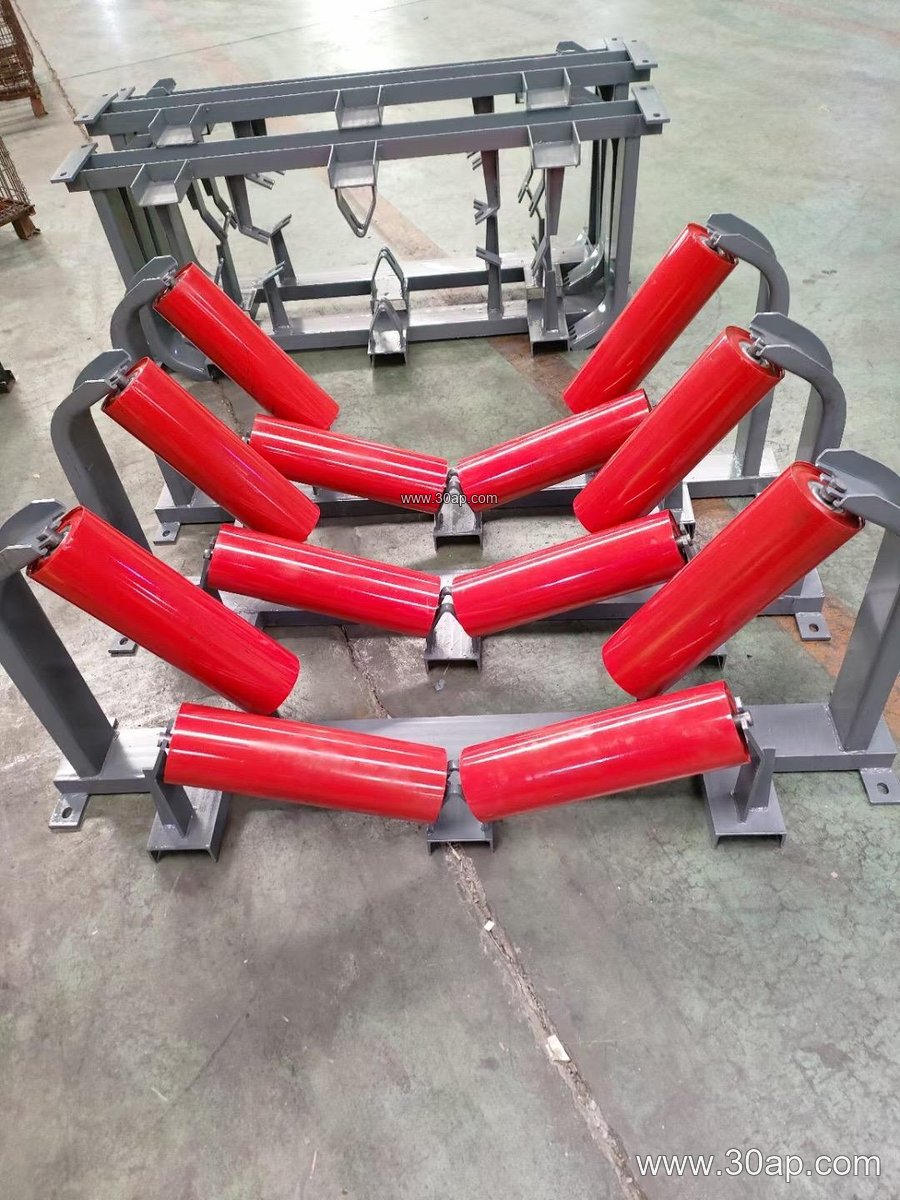
- Welded channel or angle frame with reinforced corners
- Slotted or drilled mounting holes for height and alignment adjustment
- Roller seats arranged to hold two or three impact rollers
- Optional rubber buffer pads between the rollers and the frame
- Hot-dip galvanized or painted finish for dusty, damp conditions
The trough angle of the bracket is set by the position of the roller seats. Common angles are 20, 30, 35 and 45 degrees, and an adjustable version can move between these angles so the same frame suits different belt loads. The forward tilt of the side rollers, when used, is usually about 1.5 to 2 degrees to help center the belt.
Where It Fits in the Conveyor
The bracket is installed at the transfer point, under the skirted section where the material first lands on the belt. In a limestone mine feeding a primary crusher, or in a power plant coal handling line, the impact zone may contain several brackets in a row so the shock is spread over a longer length of belt. This is especially important when the conveyor carries heavy lump material and the belt is a heavy-duty mining conveyor belt or an abrasion resistant conveyor belt that must survive both impact and sliding wear.
Matching the bracket to the belt is a matter of design rather than a fixed rule. A B800 belt at a 35 degree trough may run with Ø108 impact rollers, while a B1200 line at 45 degrees often uses Ø133 rollers, and a B1600 or B1800 conveyor at a high-tonnage transfer point may use Ø159 or Ø194 rollers. The bracket must be ordered with the correct mounting hole spacing and crossbeam length for the belt width and trough angle, since these dimensions change with the design. Belt width alone does not fix the roller diameter, and one width can be paired with more than one roller size.
Selection Notes for Buyers
When specifying an impact idler bracket, give the supplier the belt width, the trough angle, the roller diameter, the mounting hole spacing and the frame length. State the material being handled and the drop height, because a high drop of large lump ore needs a stronger buffer arrangement than a low drop of fine aggregate. Confirm whether the bracket is fixed or adjustable, and whether it will be used with rubber-cushioned impact rollers or plain steel rollers.
A few reference combinations show how the parts relate, but they are examples only and should be confirmed against the actual conveyor design:
| Belt width | Trough angle | Roller diameter | Typical location |
|---|---|---|---|
| B650 | 30 degrees | Ø89 | Small aggregate transfer |
| B800 | 35 degrees | Ø108 | Sand and gravel line |
| B1000 | 35 degrees | Ø133 | Cement plant clinker |
| B1200 | 45 degrees | Ø133 | Coal preparation plant |
| B1400 | 45 degrees | Ø159 | Iron ore crushing station |
| B1600 | 45 degrees | Ø159 or Ø194 | Port ship loading |
These values are common reference points, not universal specifications. The final choice depends on the conveyor layout, the material lump size and the belt construction.
Maintenance and Matching Parts
Check the bracket for loose bolts, cracked welds and worn rubber cushions during routine inspections. A bracket that has shifted can cause the belt to misalign, and worn impact rollers can let the belt sag into the frame at the loading point. Keep the impact zone clean, because spilled material packed around the bracket can change the roller height and stress the frame.
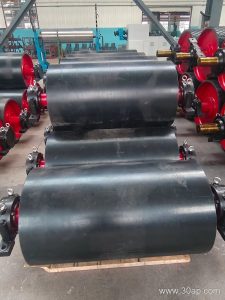
The bracket works together with other conveyor components. A well-chosen conveyor belt with good impact resistance reduces the load on the bracket, and matching idler roller sizes keeps the belt profile steady. The pulley at the drive end is a separate item and is not interchangeable with the impact bracket, just as a bend pulley and a tail pulley serve different positions. For heavy loading zones, buyers often pair the bracket with an impact resistant conveyor belt, a flame retardant conveyor belt in coal service, or a steel cord conveyor belt where tension is high, and they confirm the roller and bracket dimensions with the conveyor designer before ordering.