What the Head Drive Pulley Does
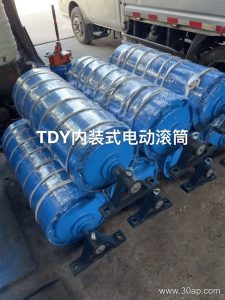
The head drive pulley is the powered drum at the discharge end of a belt conveyor. It grips the conveyor belt, transmits torque from the gearbox or motor, and sets the belt in motion. Because it sits at the head, it also sheds material as the belt turns over, so its surface and lagging often face abrasive conditions. In a quarry, a coal washing plant, or a cement clinker line, this pulley is the point where drive force enters the system, and its condition affects belt tracking, slip, and overall uptime.
How It Is Built
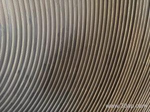
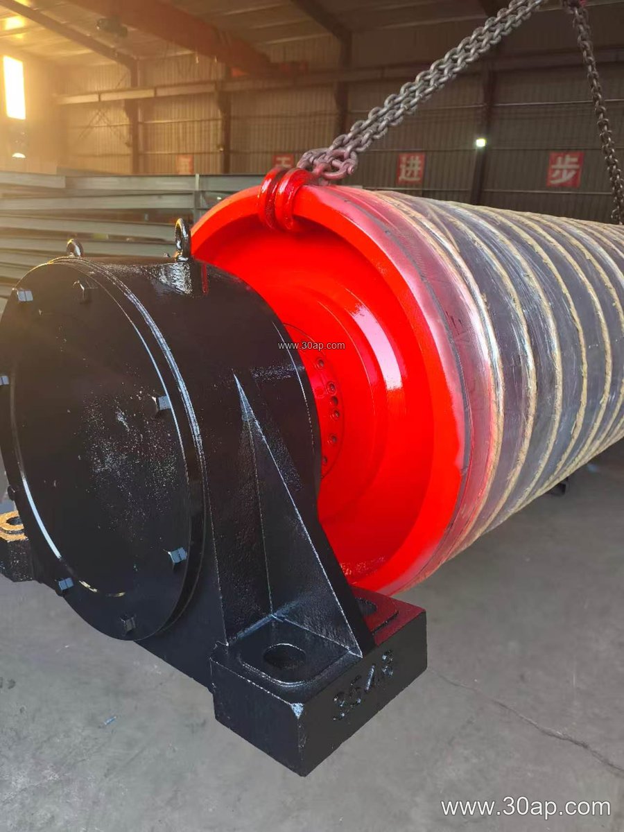
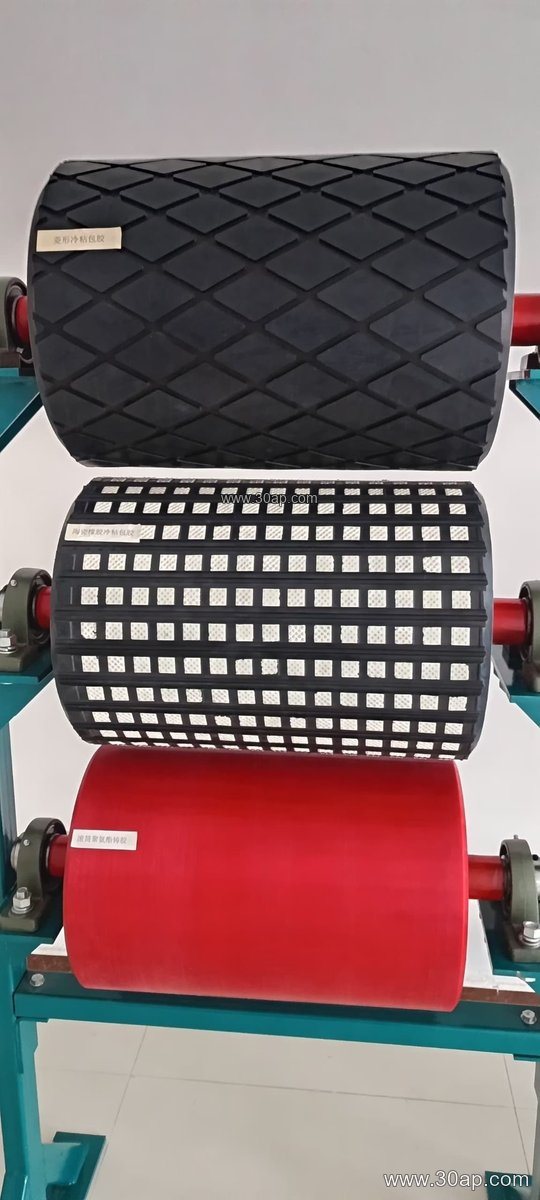
A typical head drive pulley combines a steel shell, end discs, a shaft, and bearing housings. The shell may be machined smooth or covered with lagging to raise friction. Common surface forms include plain finish, cast rubber, cold-bonded rubber, hot vulcanized rubber, diamond grooving, herringbone grooving, and ceramic lagging. Lagging thickness is often 8, 10, 12, 15, or 20 mm, selected according to belt tension and material carryback. The shaft is sized by torque and load, not by belt width alone, so diameters such as Ø50 to Ø200 mm appear across different drive designs.
Sizes and Common Combinations
Head drive pulleys are built around belt width and required torque. Shell diameters commonly range from Ø200 to Ø1800 mm, while face widths usually exceed the belt width to allow for tracking. The table below gives reference combinations; these are examples, not fixed rules, and final dimensions are set by the conveyor designer.
| Belt width | Typical pulley face width | Example shell diameter |
|---|---|---|
| B400 | approx. 500 mm | Ø200–Ø315 |
| B500 | approx. 600 mm | Ø250–Ø400 |
| B650 | approx. 750 mm | Ø315–Ø500 |
| B800 | approx. 950 mm | Ø400–Ø630 |
| B1000 | approx. 1150 mm | Ø500–Ø800 |
| B1200 | approx. 1400 mm | Ø630–Ø1000 |
| B1400 | approx. 1600 mm | Ø800–Ø1250 |
| B1600 | approx. 1800 mm | Ø1000–Ø1400 |
| B1800 | approx. 2000 mm | Ø1250–Ø1600 |
| B2000 | approx. 2200 mm | Ø1400–Ø1800 |
Combinations such as B800 × Ø500 or B1200 × Ø1000 are common in practice, but the same belt width can work with different diameters depending on speed, tension, and space. Shaft diameter follows the torque calculation; a B650 pulley might use a Ø80 mm shaft in one drive and a larger shaft in another.
Where It Fits in the Plant
Head drive pulleys appear in primary crushing circuits, overland conveyors, and transfer points. In a sand and gravel line, the head pulley at the discharge of a long incline conveyor must handle both drive tension and abrasive dust. In a power plant coal handling system, lagging choice matters because fine coal can polish a plain shell and cause slip. The pulley works alongside the conveyor belt, idler rollers, and conveyor brackets, but it is not a tail pulley or a bend pulley; those serve different positions and duties. A bend pulley changes belt direction without driving, and a tail pulley supports the return end. Comparing them helps clarify why the head drive pulley carries the main drive load.
Selection and Maintenance Notes
Buyers should confirm belt width, belt speed, required torque, and the ambient conditions before choosing lagging. Diamond or herringbone grooving can help evacuate water and fines, while ceramic lagging suits high-wear discharge points. Check that the pulley face width matches the conveyor frame and that the shaft and bearing housings fit the existing conveyor bracket. During operation, watch for belt slip, lagging wear, and material buildup on the shell. Regular inspection of the head drive pulley, together with the idler rollers and belt, keeps the conveyor running smoothly in mining, cement, and aggregate applications.