What an Intermediate Bend Pulley Does
An intermediate bend pulley is a non-driven conveyor pulley placed between the head and tail of a conveyor to guide the conveyor belt around a change in direction. Instead of driving or tensioning the belt, it redirects it, usually increasing the wrap angle on another pulley downstream or steering the return strand around an obstacle such as a chute, structure, or transfer point. In mining, quarrying, cement plants and power station coal handling, this kind of routing pulley often sits in the return run, where space is tight and the belt must follow the layout rather than a straight line.
Because it does not transmit drive torque, an intermediate bend pulley is usually grouped with the other turning pulleys of a conveyor. It should not be confused with a drive pulley, which transfers power to the belt, or a tail pulley, which sits at the loading end and supports belt alignment. A bend pulley can also be a separate unit from a tension pulley, even though both may share similar dimensions.
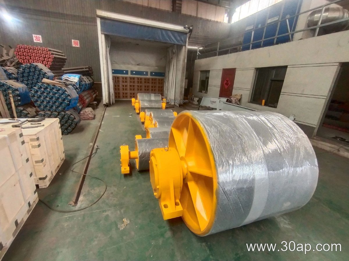
Construction and Surface Options
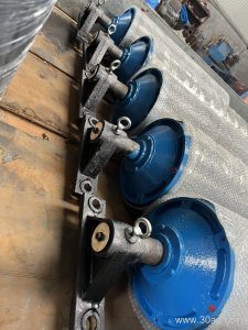
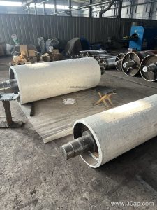
The body is normally a welded steel drum with a machined shell, end discs and a through shaft supported by two bearing housings. The shaft is sized by torque and radial load rather than by belt width alone, so two conveyors with the same belt width may use quite different shaft diameters. Common shaft sizes include Ø50, Ø60, Ø70, Ø80, Ø90, Ø100, Ø120 and larger, while shell diameters often fall in the Ø200 to Ø1000 range depending on layout and belt stiffness.
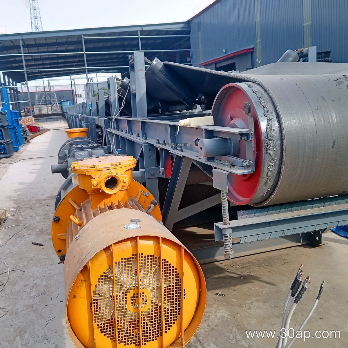
Surface treatment matters when the pulley contacts the belt with a reasonable wrap angle. Plain finish is adequate for many light-duty redirects; rubber lagging, including cold-bonded, hot-vulcanized, diamond and ceramic forms, can improve grip and protect the shell where slip or abrasive dust is present. Lagging thickness is commonly 8, 10, 12, 15 or 20 mm. For a bend pulley, plain or lightly lagged shells are often enough because the goal is guidance, not traction.
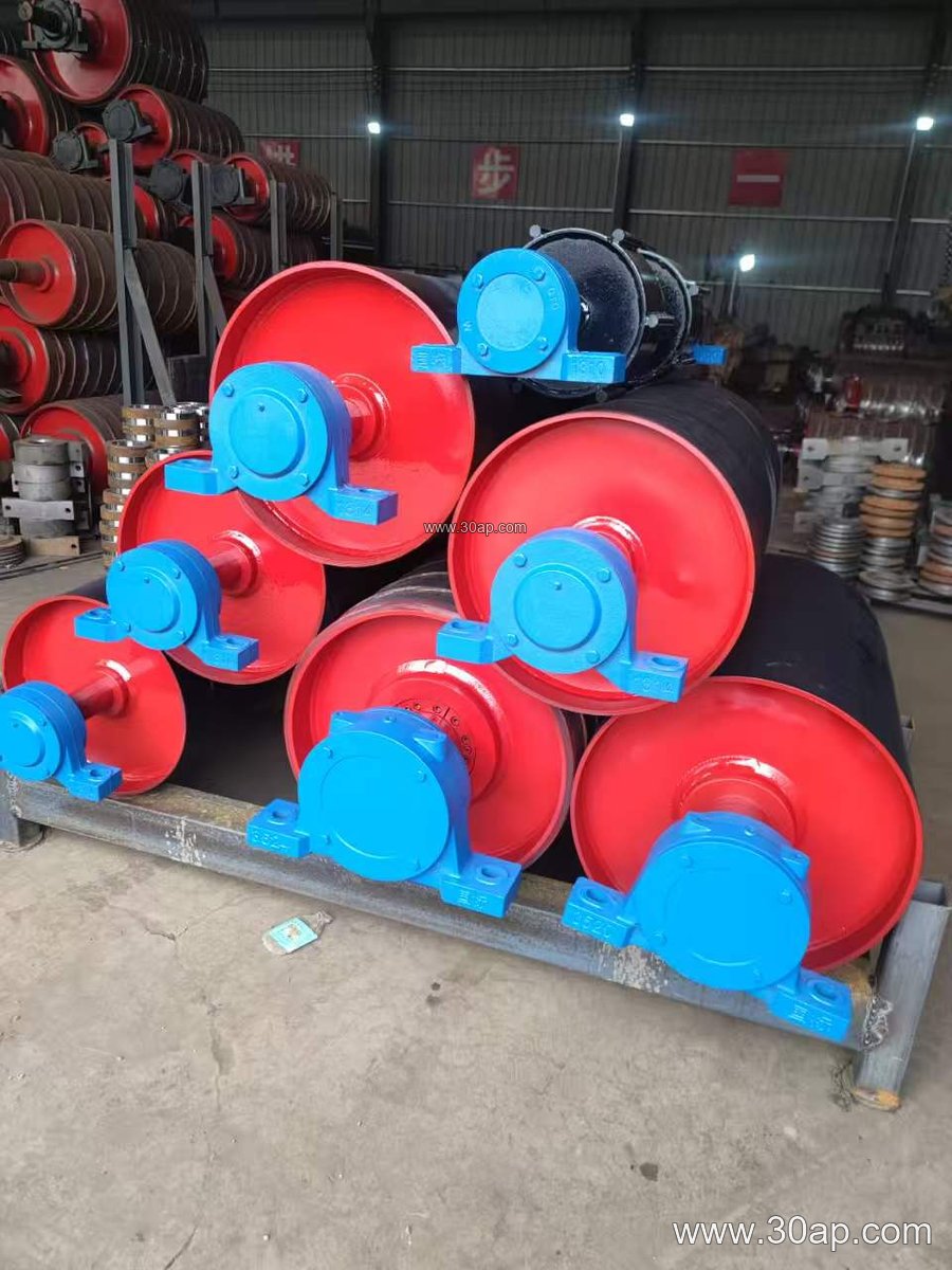
- Drum shell with welded end discs and a machined face
- Through shaft with self-aligning bearing housings and seals
- Optional lagging: plain, rubber, diamond or ceramic
- Face width usually slightly wider than the belt it guides
Typical Sizes and Dimensional Reference
The table below gives reference combinations often seen in layout drawings. These are examples, not fixed rules; a given belt width can work with more than one shell diameter, and the final choice follows belt tension, wrap angle and available space.
| Belt width | Typical pulley face width | Example shell diameter |
|---|---|---|
| B500 | about 600 mm | Ø250 or Ø315 |
| B650 | about 750 mm | Ø315 or Ø400 |
| B800 | about 950 mm | Ø400 or Ø500 |
| B1000 | about 1150 mm | Ø500 or Ø630 |
| B1200 | about 1400 mm | Ø630 or Ø800 |
| B1400 | about 1600 mm | Ø800 or Ø1000 |
When specifying, state the belt width, the required wrap angle, the belt path and the available space between frames. A small shell diameter saves room but increases belt bending stress, so the layout and belt construction should be checked together.
Where It Fits in the Conveyor Layout
In a limestone quarry or a sand and aggregate line, an intermediate bend pulley may be installed on the return strand to lift the belt over a walkway or to route it under a transfer chute. In a coal handling plant, it can help keep the return belt clear of structural steel and idler roller frames. The pulley is usually mounted on conveyor brackets fixed to the stringer or to a separate frame, and its alignment with the adjacent pulleys and troughing idlers affects belt tracking.
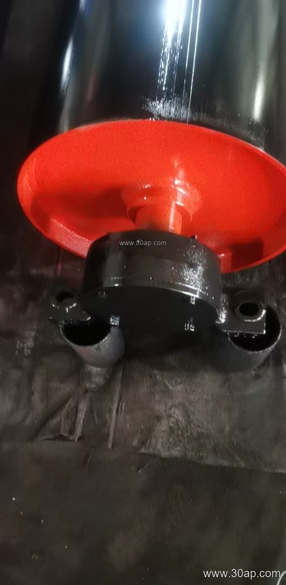
A bend pulley is not a substitute for a drive pulley, a tail pulley or a tension pulley; each has a distinct role. In some layouts, a wing pulley or a self-cleaning roller is used nearby to shed sticky material, but those are separate components with their own duties.
Buyer Checklist
- Confirm the function: redirect only, or redirect plus tension?
- Provide belt width, belt type and the expected wrap angle
- State the shaft load and torque so the shaft and bearings can be sized
- Choose lagging only where grip or wear protection is actually needed
- Check face width against belt width and confirm clearance to frames and chutes
- Ask for machining and balance tolerances, bearing type and sealing arrangement
For a cement plant, a power station or a port bulk terminal, the same intermediate bend pulley may look similar across projects, yet the bearing selection and lagging decision should follow the actual duty. Sharing the conveyor layout drawing and the belt specification early usually avoids a pulley that fits the shaft but not the belt path.