What a Head Drive Pulley Does
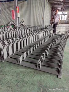
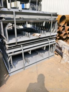
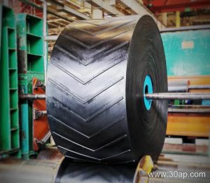
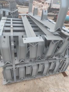
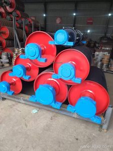
The head drive pulley is the power-transmitting drum at the discharge end of a conveyor. It grips the conveyor belt, pulls the loaded strand, and transfers torque from the drive motor and gearbox to the belt. Because it sits at the head of the conveyor, it is sometimes called a head pulley or drive drum, but it should not be confused with a tail pulley, which turns freely at the loading end, or a bend pulley, which only changes belt direction. In a typical arrangement, the head drive pulley works together with conveyor idler rollers, a conveyor bracket, and the belt itself to keep material moving from the load point to the discharge point.
Construction and Key Components
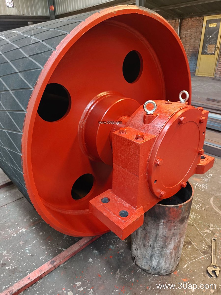
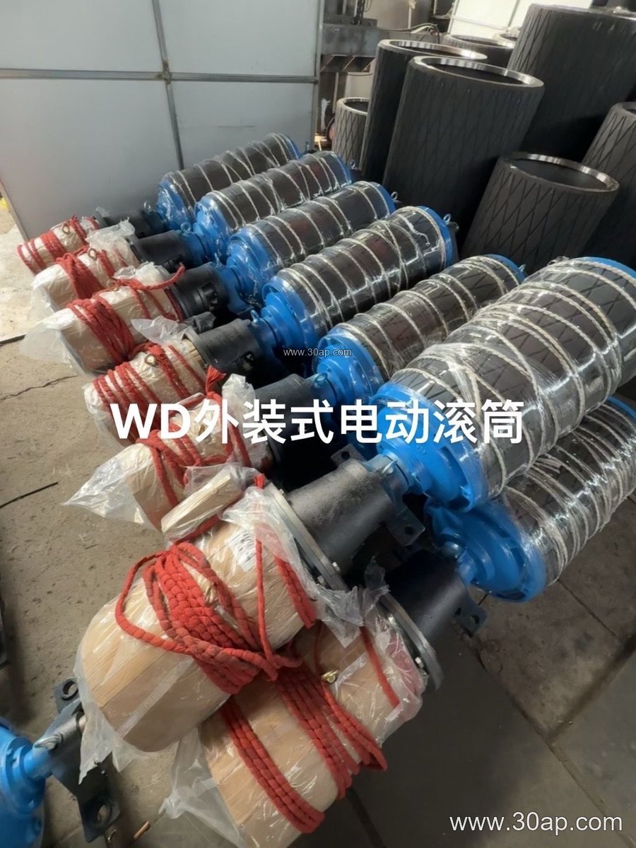
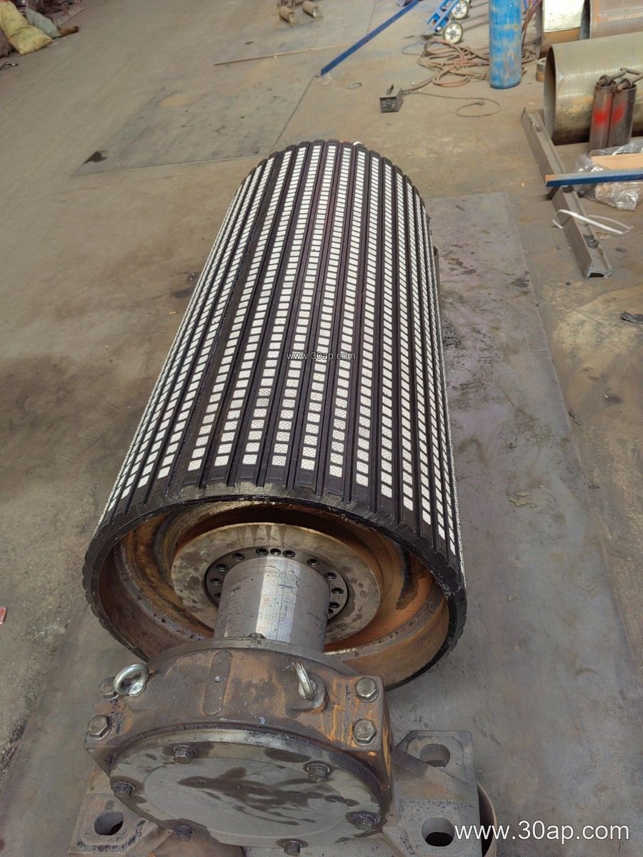
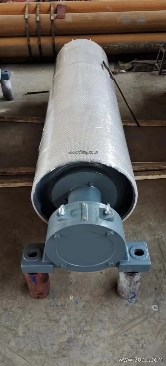
A head drive pulley is built around a cylindrical shell, usually with welded end discs and a shaft that runs through the center. The shaft is supported by bearings mounted in plummer blocks or a conveyor bracket. The shell may be plain steel or covered with rubber, ceramic, or other lagging to improve grip. Common surface forms include smooth, cast rubber, cold-bonded rubber, hot-spliced rubber, diamond lagging, herringbone lagging, ceramic lagging, and flat rubber. Lagging thickness is often 8, 10, 12, 15, or 20 mm, depending on the duty. The pulley is normally larger in diameter than a tail or bend pulley because it must transmit torque and maintain belt wrap.
Where It Is Used
Head drive pulleys appear in many bulk material handling systems. In a coal preparation plant, they drive the main belt that carries raw coal to the wash box. In a limestone quarry or aggregate line, they power the primary discharge conveyor after crushing. In a cement plant, they move clinker or raw meal. In a power plant, they handle coal on the yard conveyor. The same principle applies in a port bulk terminal, a steel mill sinter line, or a tunnel mucking conveyor. In each case, the head drive pulley is the main traction point, while conveyor idler rollers support the belt along the route.
Sizing and Selection Basics
Buyers should think in terms of belt width, pulley diameter, shaft diameter, and lagging type rather than a single fixed rule. Belt width and pulley diameter are related but not locked one-to-one. A B800 belt might run on a Ø500 head drive pulley in one conveyor and a larger diameter in another, depending on belt speed, torque, and wrap angle. The table below shows common reference combinations; these are examples, not mandatory matches.
| Belt Width | Typical Pulley Diameter | Common Face Width |
|---|---|---|
| B400 | Ø200–Ø315 | ~500 mm |
| B500 | Ø250–Ø400 | ~600 mm |
| B650 | Ø315–Ø500 | ~750 mm |
| B800 | Ø400–Ø630 | ~950 mm |
| B1000 | Ø500–Ø800 | ~1150 mm |
| B1200 | Ø630–Ø1000 | ~1400 mm |
| B1400 | Ø800–Ø1250 | ~1600 mm |
Shaft diameter is determined by torque and load, not by belt width alone. Common shaft sizes include Ø50, Ø60, Ø70, Ø80, Ø90, Ø100, Ø120, Ø140, Ø160, Ø180, and Ø200 mm. A B1200 × Ø1000 head drive pulley might use a Ø160 shaft in one design and a different size in another. The buyer should provide the conveyor duty, belt speed, motor power, and wrap angle so the pulley maker can calculate the shaft and bearing requirements.
Surface Choices and Maintenance
Lagging selection depends on the material and environment. Diamond or herringbone rubber lagging helps shed water and fine particles in a wash plant or port terminal. Ceramic lagging may be chosen where oily or wet conditions reduce friction. Plain steel is used in clean, low-torque applications. During operation, check that the head drive pulley turns freely, that lagging is not worn through, and that belt tracking is correct. Worn lagging can cause slip, especially in a sand and gravel line or a fertilizer handling system. Keep the conveyor belt tensioned and the conveyor idler rollers aligned to reduce uneven wear on the pulley face.
For any project, specify the head drive pulley by belt width, pulley diameter, face width, shaft diameter, lagging type, and bearing arrangement. Use the reference data as a starting point, then confirm the final dimensions with the pulley manufacturer based on the actual conveyor design.