What a Belt Conveyor Idler Does on the Line
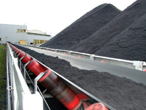
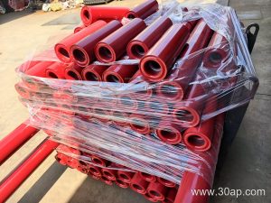
A belt conveyor idler is the rotating roller assembly that supports the conveyor belt and the material load along the carrying and return runs. In a sand and gravel plant or a coal handling system at a power plant, these rollers are the most numerous wearing parts on the conveyor. Each idler roller turns with the belt, so friction stays low and the belt keeps a steady line instead of dragging over a fixed support.
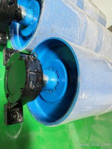
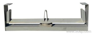
The idler works together with the conveyor belt, the conveyor pulley at the head and tail, and the conveyor bracket that fixes each station to the frame. Drive, tail and bend pulleys pull and redirect the belt; the idler only supports it. That division matters when a buyer orders spare parts, because pulleys and idlers are not interchangeable items.
How an Idler Is Built
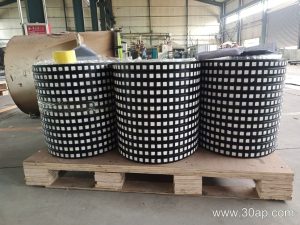
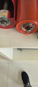
A typical unit has a steel tube shell, a shaft, bearing housings at both ends, and a sealing arrangement that keeps dust and water out. The shell may be plain steel, nylon coated, ceramic covered, or fitted with rubber rings for impact duty. Bearing size is matched to the load and speed by the designer; common bearing numbers include 6204, 6205, 6305, 6306, 6308 and 6310, but no single bearing is tied to one roller diameter.
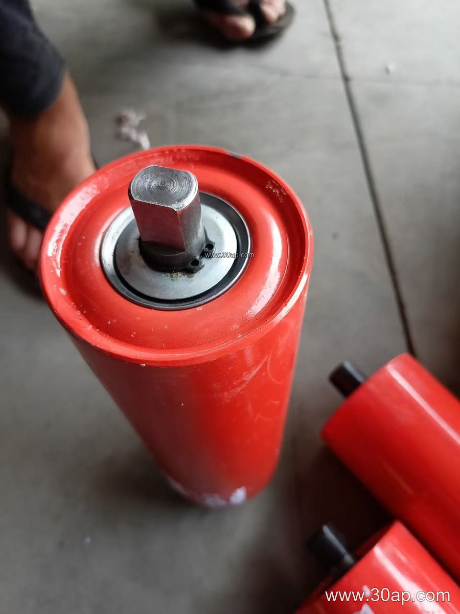
Sealing quality often decides service life in a limestone mine or cement plant, where fine abrasive dust is constant. A labyrinth seal with grease retention is a practical reference point when comparing offers.
Common Types and Where They Sit
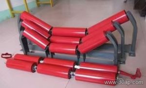
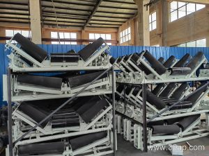
- Troughing idlers in two- or three-roll sets form the belt into a trough on the carrying side, usually at 20, 30, 35 or 45 degrees.
- Impact idlers with rubber rings sit under the loading point to absorb falling lump impact.
- Return idlers, flat or V-shaped, support the empty belt on the return run.
- Transition idlers ease the belt from the pulley curve into the full trough.
- Self-aligning idlers, including friction and tapered designs, correct minor belt drift; a slight forward tilt of about 1.5 to 2 degrees is sometimes used for the same purpose.
- Spiral idlers help shed sticky material on the return side.
Reference Dimensions Buyers Often Ask About
The table below gives common reference values. Actual roller length depends on belt width, trough angle and roll arrangement, and side rolls may differ from the centre roll.
| Belt width | Typical roll length, three-roll trough (mm) | Common idler diameters (mm) |
|---|---|---|
| B500 | 200 | 63, 76, 89 |
| B650 | 250 | 76, 89, 102 |
| B800 | 315 | 89, 102, 108 |
| B1000 | 380 | 108, 127, 133 |
| B1200 | 465 | 108, 127, 133, 159 |
| B1400 | 530 | 127, 133, 159 |
| B1600 | 600 | 133, 159, 178 |
| B1800 | 670 | 159, 178, 194 |
| B2000 | 750 | 159, 178, 194, 219 |
These figures are examples, not fixed pairings. A wider belt does not automatically dictate one shaft diameter, and shaft size should come from the idler manufacturer’s load calculation.
What to Check Before Ordering
Start with the belt width and the trough angle, then confirm the roll length and the mounting gap on the existing conveyor bracket. State the material being handled, since iron ore, sinter, fertiliser and grain place very different demands on the roller surface and seal. Give the belt speed and the load per station so the supplier can confirm the bearing and tube thickness.
On site, keep a few spare idler rollers of each station type, check for seized bearings and worn shells during routine walks, and replace a damaged roller before it damages the conveyor belt. Correct alignment and free rotation are the main things to watch in a quarry, a washing plant or a port terminal alike.