What a Head Pulley Assembly Does
A head pulley assembly is the drive end of a belt conveyor system. It sits at the discharge point, grips the conveyor belt, and pulls the loaded strand forward. In a quarry, a coal preparation plant, or a cement clinker line, this assembly often determines how smoothly material leaves the belt and enters the next stage. The head pulley is sometimes called the drive pulley or discharge pulley, and that naming is accurate because it reflects its position and function. A tail pulley, by contrast, returns the belt at the opposite end, while a bend pulley changes direction without driving. Those are different roles and should not be used as interchangeable labels.
How the Assembly Is Built
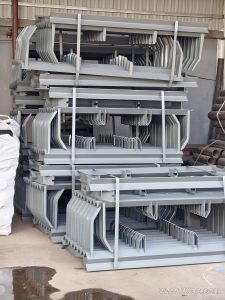
The core is a cylindrical shell, usually machined from steel tube or plate, with end discs welded in place. A shaft runs through the center and is supported by bearing housings mounted on a conveyor bracket or frame. The shell surface may stay plain or receive a rubber lagging. Common surface forms include smooth finish, cold-bonded rubber, hot vulcanized rubber, diamond grooving, herringbone grooving, and ceramic lagging. Lagging thickness is often 8 mm, 10 mm, 12 mm, 15 mm, or 20 mm depending on grip and wear conditions. The assembly also includes keyed connections, locking elements, and sometimes a torque arm when an electric drum is used instead of an external drive.
Where It Fits in Bulk Material Handling
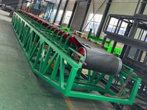
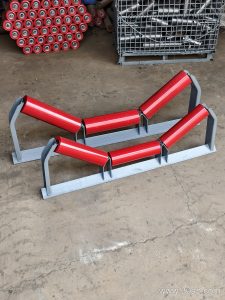
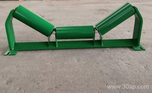
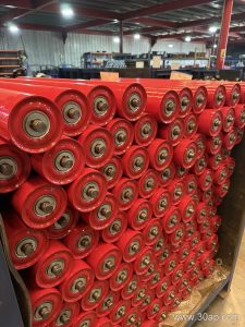
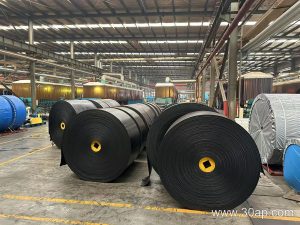
You will find this assembly in sand and gravel plants, iron ore concentrators, power station coal conveying, port bulk terminals, and fertilizer or grain silo systems. It works together with the conveyor belt, idler rollers, and support brackets along the entire line. In a crushing and screening circuit, the head pulley discharges crushed rock onto a transfer chute. In a tunnel boring operation, it helps move muck out of the heading. The assembly must match the belt width and the duty cycle, not just the tonnage per hour.
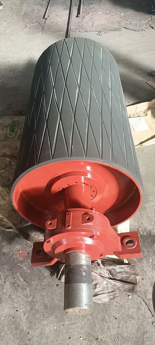
Key Parameters Buyers Should Check
Belt width and pulley diameter are linked by design, but they are not a fixed one-to-one match. A B800 belt may run on a head pulley with a diameter from around Ø500 to Ø800, while a B1200 system might use Ø800, Ø1000, or larger depending on belt tension and wrap angle. The table below shows common reference combinations, not mandatory pairings.
| Belt Width | Typical Pulley Diameter | Typical Face Width |
|---|---|---|
| B400 | Ø200 – Ø320 | about 500 mm |
| B500 | Ø250 – Ø400 | about 600 mm |
| B650 | Ø315 – Ø500 | about 750 mm |
| B800 | Ø400 – Ø630 | about 950 mm |
| B1000 | Ø500 – Ø800 | about 1150 mm |
| B1200 | Ø630 – Ø1000 | about 1400 mm |
| B1400 | Ø800 – Ø1250 | about 1600 mm |
| B1600 | Ø1000 – Ø1400 | about 1800 mm |
Shaft diameter is selected from torque and load calculations, not directly from belt width. Common shaft sizes include Ø50, Ø60, Ø70, Ø80, Ø90, Ø100, Ø120, Ø140, Ø160, Ø180, and Ø200. A larger shaft may be needed for high-tension or heavy-duty service. The pulley face is normally wider than the belt, so a B650 belt often uses a face width near 750 mm.
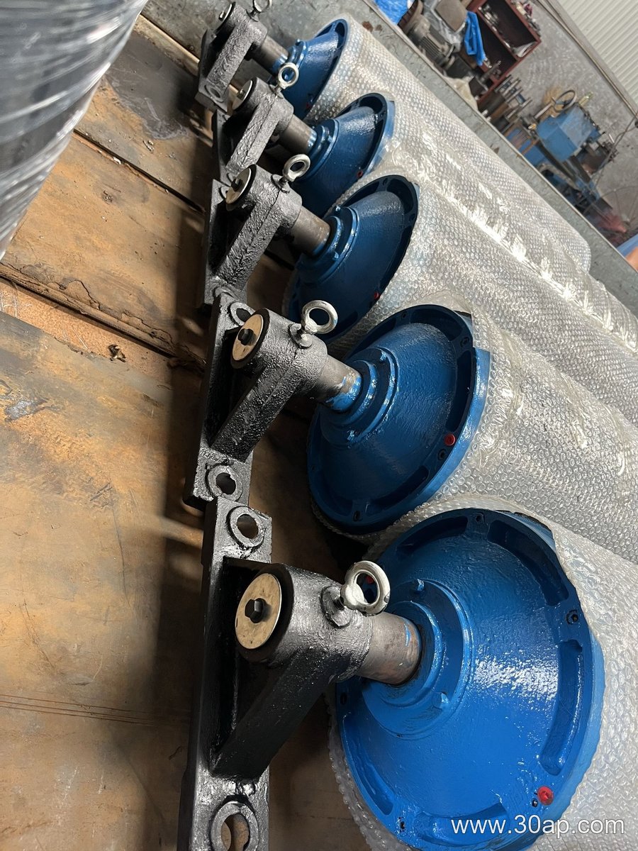
Lagging and Surface Selection
For dry, clean material, a plain or lightly lagged surface may be enough. Wet or muddy conditions in a sand and gravel wash plant usually call for diamond or herringbone rubber lagging to shed water. Ceramic lagging is chosen where abrasive fines and high slip risk exist, such as in a coal handling system. Hot vulcanized rubber gives a strong bond for continuous duty, while cold-bonded rubber is often used for replacement work. The right choice depends on belt speed, wrap angle, and the presence of oil or chemicals.
Installation and Maintenance Notes
Alignment matters. The assembly should be squared to the conveyor centerline so the belt tracks correctly. Bearing housings need proper lubrication and inspection for temperature rise or noise. Lagging should be checked for wear, gouges, and separation from the shell. When replacing a head pulley, verify the shaft key, bearing type, and mounting bolt pattern against the existing conveyor bracket. Do not assume that a bend pulley or tail pulley can substitute for the drive unit; their load paths and torque requirements differ. A spare idler roller is not a replacement for a failed head pulley assembly.
What to Specify When Ordering
- Belt width and required pulley face width
- Pulley diameter and shell thickness
- Shaft diameter, material, and keyway details
- Lagging type and thickness
- Bearing type and housing style
- Drive arrangement, if an electric drum or gearbox is involved
- Operating environment, such as dusty, wet, or corrosive
Accurate specifications help the supplier match the assembly to the conveyor, whether it serves a limestone mine, a copper concentrator, or a concrete batching plant. The head pulley assembly is a wear part and a drive component at the same time, so it deserves the same attention as the belt and the idler rollers it works with.