What a Motor-Driven Pulley Is
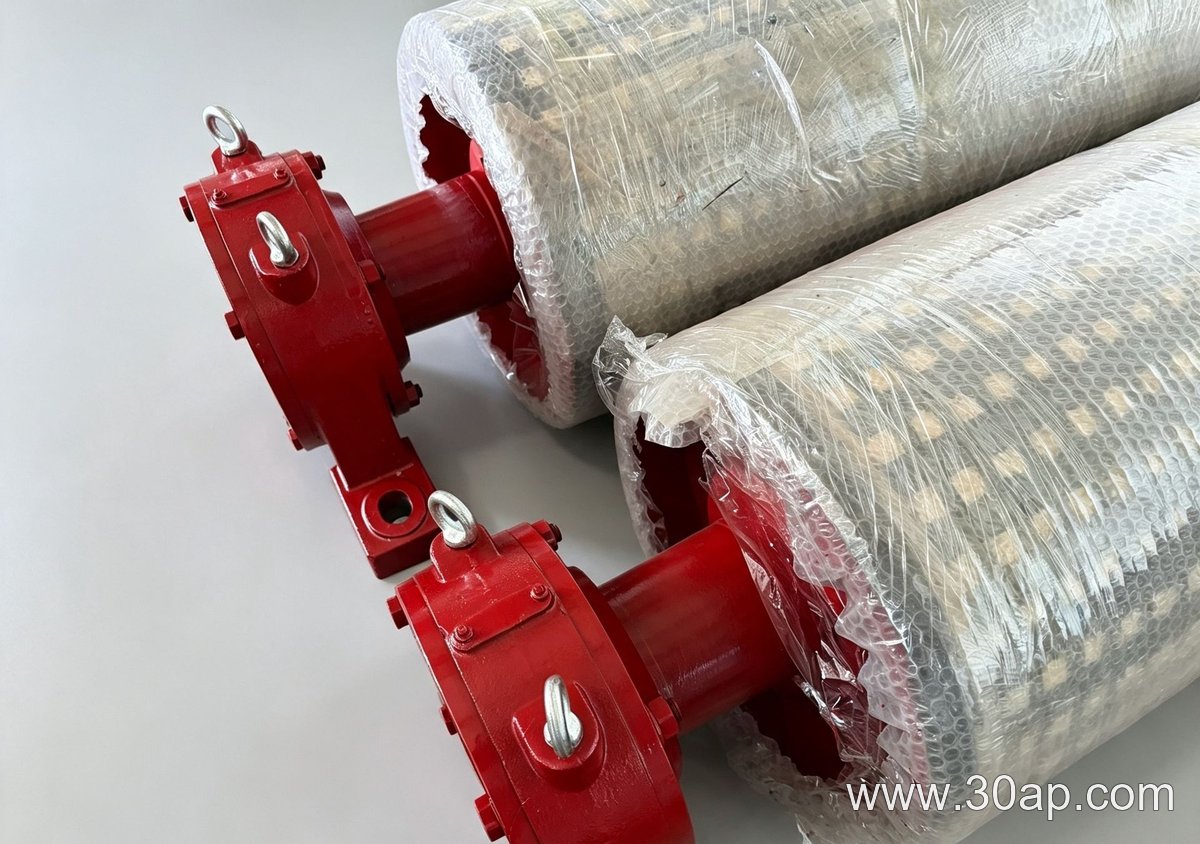
A motor-driven pulley, often called a drum motor or an internal motor pulley, is a conveyor pulley with the motor and gearbox built inside the drum shell. Instead of mounting a separate motor and reducer outside the conveyor frame, the drive is enclosed within the pulley body. The rotating shell contacts the conveyor belt directly, so the unit acts as both the driving element and the supporting drum. In many conveyor layouts, this assembly is the head or drive pulley, meaning it transmits torque to move the belt and its load. It is not a tail pulley, bend pulley, or take-up pulley, though it may sit at a head station that also includes a conveyor bracket to hold the shaft ends.
Construction and Main Parts
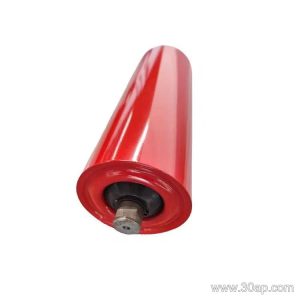
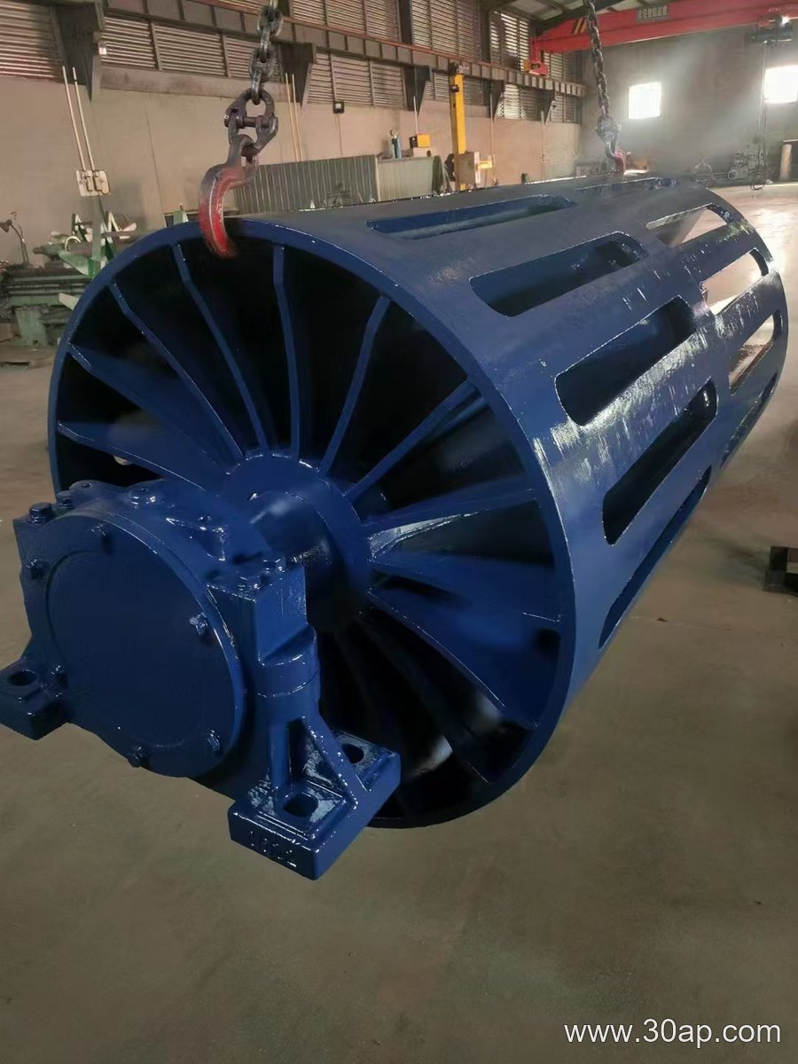
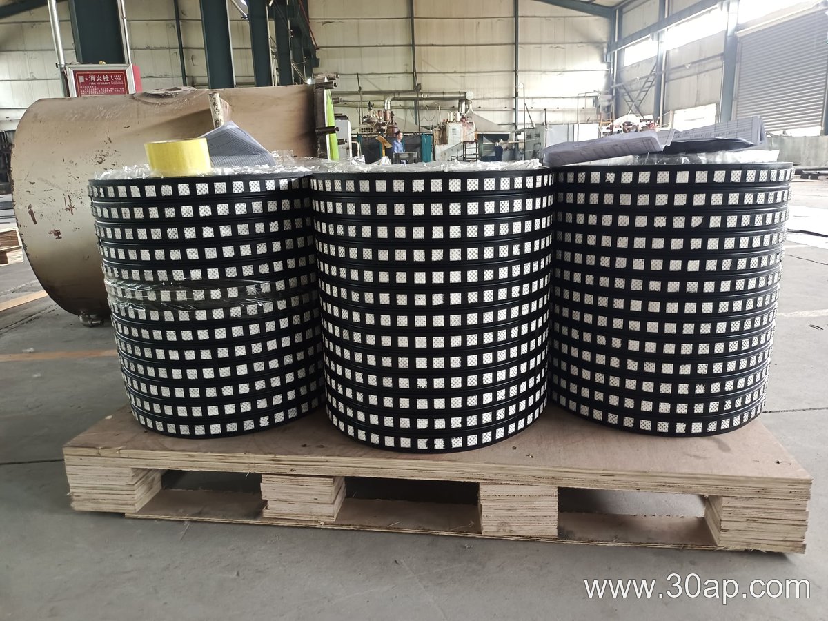
The housing is usually a steel cylinder with machined end discs. Inside, an electric motor, a gear stage, and bearings operate in an oil bath or grease-lubricated chamber. The shaft does not rotate; the shell turns around it. Power and control cables enter through a stationary shaft end, often through a hollow bore. Surface finish and lagging can be added to improve grip. Common surface options include plain finish, cold-bonded rubber, hot-vulcanized rubber, diamond lagging, herringbone lagging, ceramic lagging, and flat rubber. Lagging thickness is often 8, 10, 12, 15, or 20 mm, depending on the duty. The outer shell diameter may range from Ø200 to Ø1800 in heavy-duty designs, while belt widths for conveyors that use such pulleys commonly run from B400 up to B2400. A belt width does not dictate a single drum diameter; for example, B800 can be paired with Ø500 in one conveyor and with a larger drum in another, depending on belt tension and speed.
Where It Fits in a Conveyor
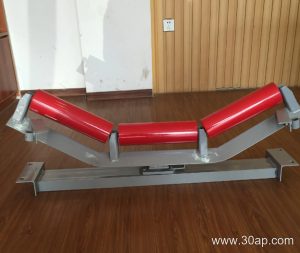
This drive style is found in space-limited installations, dusty plants, and outdoor lines where an exposed motor and coupling would need extra guarding. Typical locations include aggregate crushing and screening plants, coal handling at power stations, cement clinker lines, and bulk terminals. In these settings, a motor-driven pulley often serves as the head pulley at the discharge end, driving the loaded conveyor belt. A separate idler roller may support the belt on the return strand, and a bend pulley may change the belt path, but the motorized drum remains the torque source. Because the drive is sealed, it can suit washdown areas and environments with fine dust. However, it is not a direct substitute for a tail pulley, which normally only redirects the belt, or for a bend pulley, which changes direction without driving. Those components have different loads and different bearing arrangements.
Common Sizes and Combinations
The table below lists reference combinations that appear in conveyor design. These are examples, not fixed rules or universal stock sizes. Diameter and shaft diameter are selected by torque, belt tension, and bearing life, not by belt width alone. A shaft diameter such as Ø80 or Ø120 should come from the drive calculation, not from a simple width chart.
| Belt width | Example pulley diameter | Typical drum face width |
|---|---|---|
| B400 | Ø200, Ø250 | about 500 mm |
| B500 | Ø250, Ø315 | about 600 mm |
| B650 | Ø320, Ø400 | about 750 mm |
| B800 | Ø400, Ø500 | about 950 mm |
| B1000 | Ø500, Ø630 | about 1150 mm |
| B1200 | Ø630, Ø800, Ø1000 | about 1400 mm |
| B1400 | Ø800, Ø1000 | about 1600 mm |
| B1600 | Ø1000, Ø1250 | about 1800 mm |
| B1800 | Ø1250, Ø1400 | about 2000 mm |
| B2000 | Ø1400, Ø1600 | about 2200 mm |
Larger drums, such as Ø1600 or Ø1800, are sometimes used on high-capacity lines, but they require careful shaft and bearing selection. For a B1200 conveyor, a motorized drum of Ø1000 is a common example when the belt is heavy and the speed is moderate. For a B800 line, Ø500 may be enough in a short transfer, while a longer conveyor might need Ø630 or more. The face width of the drum is usually wider than the belt, so a B650 belt often runs on a drum with about 750 mm of face. This extra width helps keep the conveyor belt centered.
Buyer Checklist
- Confirm the required belt width and the actual belt tension, not just the conveyor length.
- State the duty cycle, starts per hour, and whether the drive will run fully loaded or intermittently.
- Specify the lagging type and thickness if extra grip is needed. A diamond or herringbone pattern can help in wet conditions, while ceramic lagging may suit abrasive service.
- Check the available space around the head station, because an internal motor limits how the conveyor bracket and chute can be arranged.
- Ask for the shaft diameter that matches the calculated torque. Do not assume a fixed shaft size from the belt width.
- Plan for maintenance access to the terminal box and oil plugs, even though the drive itself is enclosed.
- Verify that the pulley will act as a drive pulley, not as a tail or bend pulley, and that the control system can handle the motor starting characteristics.
A motor-driven pulley can simplify a conveyor drive station and reduce exposed parts. The key is to match the drum to the belt, the load, and the surrounding structure, using engineering data rather than a single size rule.