Calculating Idler Roller Spacing and Face Widths for Cement Plant Conveyors
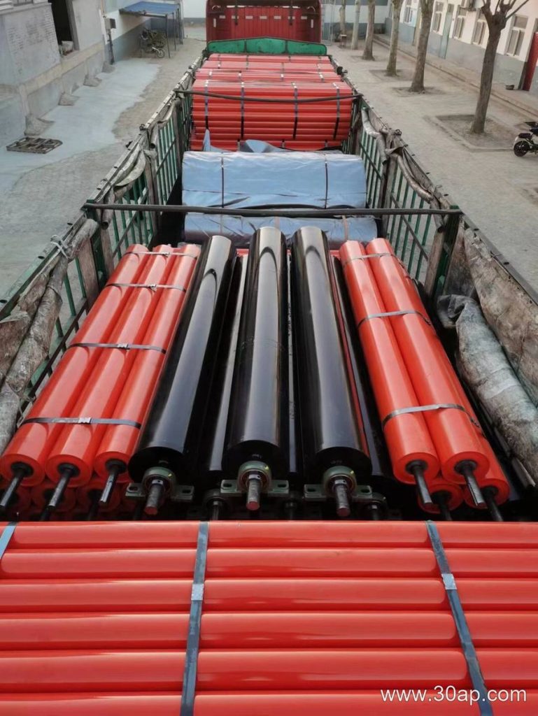
An idler roller plays a foundational mechanical role in supporting conveyor belts carrying abrasive materials like crushed limestone and clinker inside a heavy-duty cement plant. Proper mechanical design requires calculating exact physical dimensions, including shell length, shaft diameter, and longitudinal spacing between adjacent frames. When sizing these components, engineers must balance belt sag limits against maximum load capacities without exceeding the structural fatigue thresholds of the rotating assembly.
Incorrect spacing or improper dimensioning leads to severe belt mistracking, excessive friction, and premature bearing failure. To establish a reliable layout, mechanical designers rely on established formulas that account for belt tension, unit weight of the transported material, and belt speed. The following calculation steps outline how to determine appropriate dimensions for an idler roller setup in a continuous bulk handling application.
Stating Assumptions and Input Parameters
Before executing any geometric or load-based sizing calculations, engineers must define a clear set of operational baselines. For this hypothetical cement plant raw-handling conveyor, we assume the following design parameters:
- Conveyor belt width ($B$): 1200 mm
- Mass of the conveyor belt ($q_b$): 25 kg/m
- Mass of the transported material ($q_m$): 75 kg/m
- Maximum allowable belt sag ($\delta$): 2% of the idler roller spacing
- Minimum belt tension ($T_1$): 4500 N at the loading zone
- Idler roller rotational speed limit: 550 RPM
These values establish the baseline physical envelope. The mass acting upon each troughing idler set is a direct function of both the moving belt and the bulk limestone resting upon its surface.
Step-by-Step Dimension and Spacing Formula
The primary calculation focuses on determining the maximum allowable spacing ($L$) between consecutive idler roller assemblies to restrict belt sag within safe engineering limits. Excessive sag increases the required drive torque and accelerates wear on the underside of the belt cover.
The formula for calculating maximum idler spacing based on belt sag is expressed as:
$L = \sqrt{\frac{384 \times E \times I \times \delta}{5 \times (q_b + q_m) \times g}}$
Where $E$ represents the belt modulus of elasticity, $I$ is the moment of inertia of the belt cross-section, $\delta$ is the allowable sag, $(q_b + q_m)$ is the total linear mass, and $g$ is gravitational acceleration ($9.81\text{ m/s}^2$). However, in practical industrial layout design, engineers frequently use a simplified load-based approach derived from permissible bearing loads and dynamic shell deflection limits:
$L_{max} = \frac{8 \times M_{allow}}{(q_b + q_m) \times g}$
Using our hypothetical parameters where the combined linear mass is $100\text{ kg/m}$, the total distributed weight per meter is approximately $981\text{ N/m}$. If the allowable bending moment ($M_{allow}$) dictated by the idler roller shaft diameter and steel grade permits a maximum center-to-center distance of $1200\text{ mm}$ under full load, the layout is locked at a $1.2\text{ meter}$ pitch along the carrying run.
Sizing Shell Length and Trough Angles
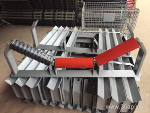
Once the longitudinal pitch is established, the physical dimensions of the individual idler roller units within the troughing bracket must be calculated. For a standard 1200 mm belt width, a three-roll troughing configuration is typically selected. The dimensions comprise one central flat roll and two inclined side rolls.
Standard sizing conventions dictate that:
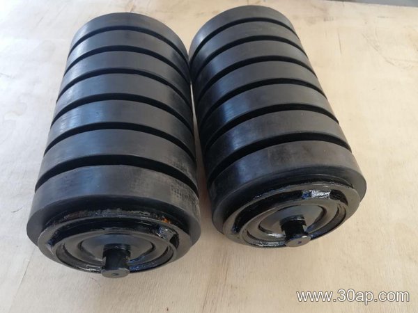
- Center roll length ($A$) matches the flat bottom width of the troughed profile, typically chosen as 465 mm.
- Wing roll length ($C$) for each inclined side is selected as 465 mm to maintain a uniform trough geometry.
- Trough angle ($\theta$) is set to 35 degrees to maximize volumetric capacity without over-stressing the transverse carcass threads of the belt.
The total active contact width of the idler roller set must span approximately 75 to 80 percent of the total belt width to ensure smooth transition profiles and prevent pinching at the wing junctions.
Verifying Dynamic Load Ratings
The final phase of the dimensional calculation requires verifying that the selected idler roller bearings can withstand the radial forces generated by the calculated spacing. The basic dynamic load rating ($C$) must be evaluated against the equivalent radial load ($P$) derived from the rotating mass and belt tension components.
$P = \frac{(q_b + q_m) \times g \times L}{2} + T_1 \times \sin(\lambda)$
Where $\lambda$ accounts for the idler bracket surcharge angle. By ensuring that the calculated equivalent radial load remains well below the catalog rating of the internal deep-groove ball bearings or tapered roller bearings, the engineering team confirms that the physical dimensions and spacing will deliver long-term reliability in demanding industrial environments.