What Pulley Custom Machining Covers
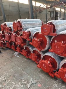
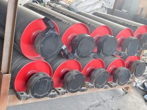
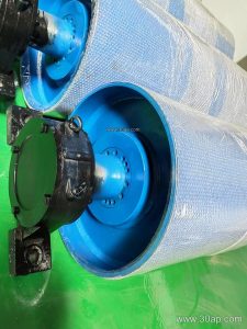
Pulley custom machining is the engineering and fabrication of conveyor pulleys to match a specific belt line, load profile, and installation envelope. Rather than forcing a standard shell and shaft into a conveyor that was designed around different tensions, a custom-machined pulley is built from the hub outward: shell diameter, face width, shaft diameter, lagging pattern, and bearing arrangement are all set by the application. This work applies to drive pulleys, tail pulleys, bend pulleys, and other positions where the pulley is a functioning part of the conveyor, not a generic rotating component.
In a quarry or aggregate line, the difference between a correctly machined drive pulley and a poorly matched one shows up as belt slip, edge wear, and shortened lagging life. The same principle holds in a coal handling plant or a cement clinker circuit. Custom machining is the process that closes the gap between the conveyor belt and the pulley that moves it.
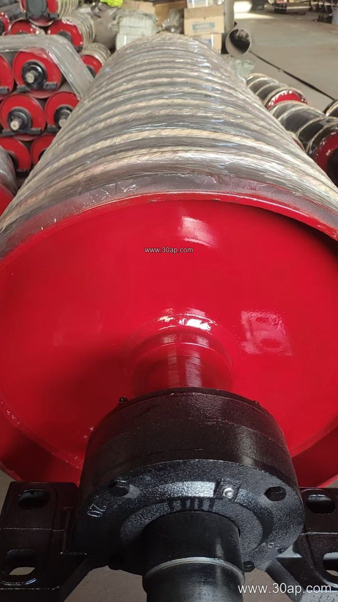
How a Custom Pulley Is Built
The usual sequence starts with the conveyor duty: belt width, belt tension, speed, and the material being carried. From there the shell is selected or rolled, the end discs are machined, and the shaft is turned to the required diameter and keyway. Common shaft diameters range from Ø50 to Ø200, but the final value is determined by torque and radial load, not by belt width alone. A B800 conveyor might use a Ø500 shell in one layout and a larger diameter in another, depending on wrap angle and tension.
Face width normally runs wider than the belt. For reference, a B650 belt often pairs with a shell face around 750 mm, a B1000 belt with roughly 1150 mm, and a B1400 belt with about 1600 mm. These are typical proportions, not fixed rules. Bearing housings, locking assemblies, and end caps are machined to suit the shaft and the conveyor bracket. The finished pulley is balanced and, where specified, lagged before delivery.
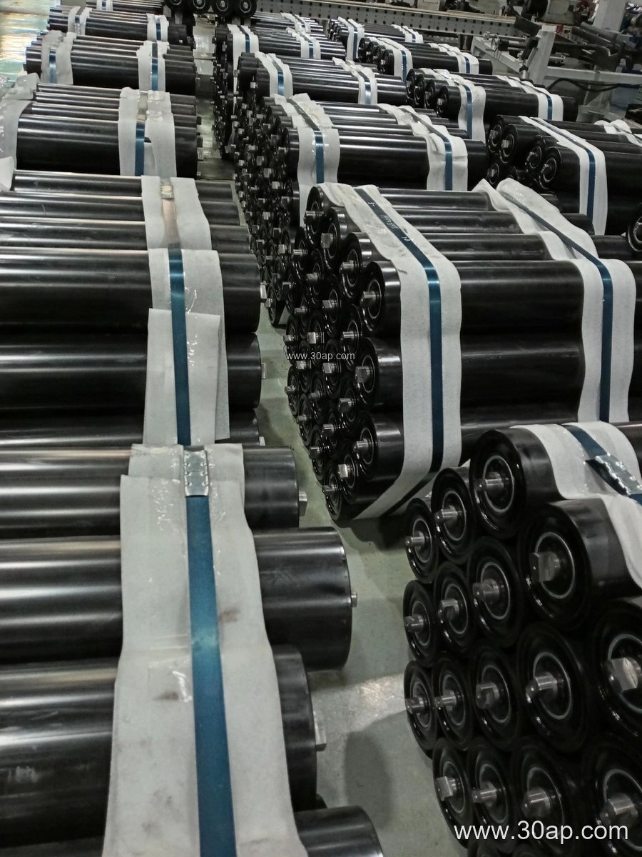
Lagging and Surface Options
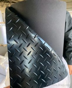
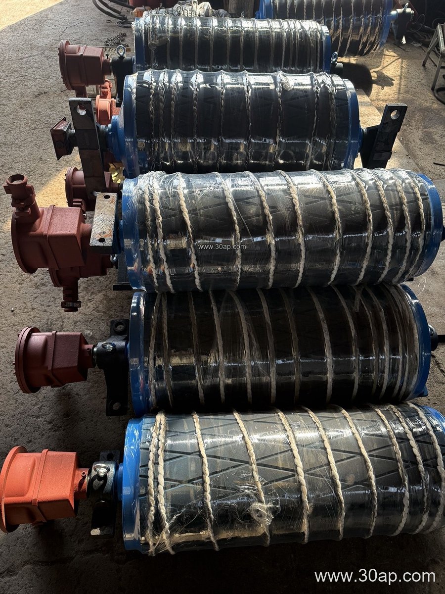
Surface form is one of the most application-specific decisions in pulley custom machining. Plain steel is used where traction is not critical. Rubber lagging, applied by cold bonding or hot vulcanizing, improves grip on the drive pulley. Diamond and herringbone patterns help shed water and fines, while ceramic lagging is chosen for high-wear drive positions in iron ore or copper ore handling. Lagging thickness commonly falls between 8 mm and 20 mm.
The right choice depends on whether the pulley is a drive, tail, or bend pulley. A drive pulley needs traction and wear resistance; a bend pulley usually needs a clean, smooth surface to guide the belt without adding unnecessary friction. This is where a custom-machined pulley earns its cost, because the lagging can be matched to the belt and the material rather than picked from a short catalog list.
Where These Pulleys Are Used
Custom-machined pulleys appear wherever a conveyor belt runs under load. In a limestone mine, the head pulley discharges crushed rock onto a transfer conveyor, while the tail pulley keeps the return strand aligned. In a power plant coal yard, drive pulleys handle high-tension belts and must resist abrasion from coal dust. Sand and gravel plants use bend pulleys to route the belt around structures, and tunnel muck lines rely on robust tail pulleys that tolerate impact and misalignment.
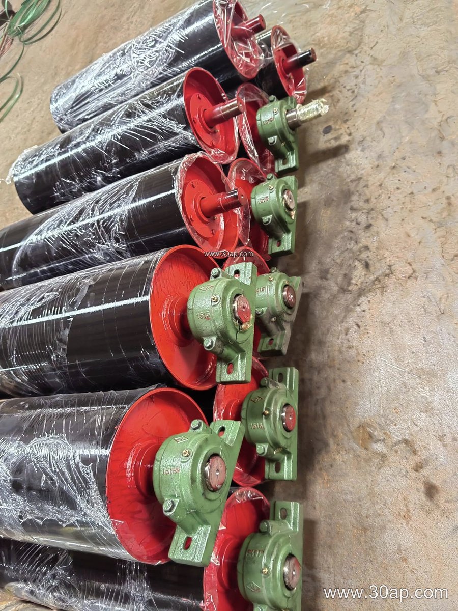
Each position places different demands on the pulley. A drive pulley in a cement plant may need a larger diameter and heavier lagging than a bend pulley a few meters away. Treating drive, tail, and bend pulleys as interchangeable is a common mistake; they perform different jobs and should be machined accordingly.
Buyer Checklist for Custom Pulley Machining
- Confirm the belt width and the required face width, remembering that the shell is usually wider than the belt.
- Provide the belt tension and speed so the shaft diameter and bearing selection can be calculated.
- State the pulley position, such as drive, tail, or bend, because it affects lagging and shell thickness.
- Specify the lagging type and thickness if traction or wear resistance matters.
- Check the shaft and bearing housing dimensions against the existing conveyor bracket and coupling.
- Ask for the balancing grade and runout tolerance if the pulley will run at higher speed.
A buyer who supplies these details gets a pulley that fits the first time. A buyer who orders by belt width alone may receive a pulley that bolts up but does not perform. For related conveyor components, matching the pulley to the conveyor belt, the idler roller set, and the conveyor bracket is part of the same engineering conversation.
Installation and Maintenance Notes
Even a well-machined pulley depends on correct installation. Shaft alignment, bearing preload, and belt tracking should be checked before the conveyor is loaded. Lagging wear, shell cracks, and keyway looseness are the usual inspection points. In abrasive service, such as a crusher conveyor or a quarry conveyor, lagging may need replacement before the shell does, which is one reason the lagging specification should be recorded at the time of order.
Custom machining does not end at delivery. Keeping the original drawing and the material and lagging details on file makes future replacement straightforward and keeps the conveyor running with the pulley it was designed around.