What a Conveyor Leg Does on a Belt System
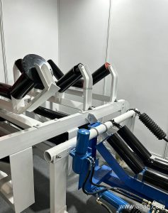
A conveyor leg is the vertical support that carries the weight of the idler frames, the belt, and the material load down to the floor or foundation. On a typical troughed carrying section, the leg works together with a cross beam and the bracket that holds the idler roller in place. In practice, the leg is the part that decides how high the belt line sits, how level it stays over long runs, and how easily the structure can be adjusted when a plant layout changes.
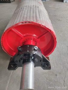
Because the leg is a structural item rather than a rotating one, it is often overlooked during planning. Yet a weak or poorly aligned leg shows up quickly as belt misalignment, uneven wear on the conveyor pulley, and vibration at the transfer points. For anyone specifying a conveyor bracket or a complete support set, the leg deserves the same attention as the rollers and the belt itself.
How a Conveyor Leg Is Built
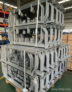
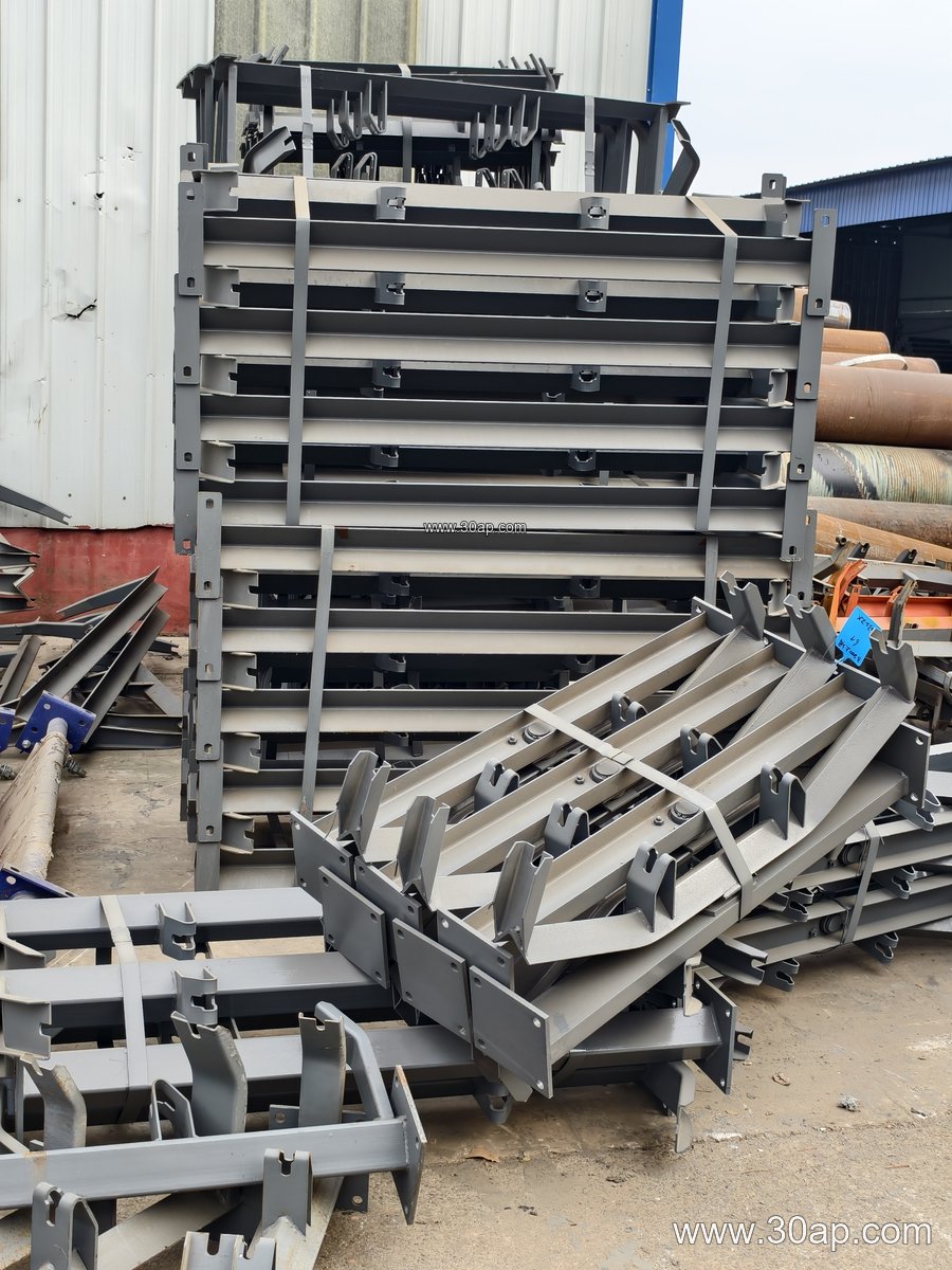
Most legs are fabricated from structural steel. Common forms include angle steel, channel steel, and folded steel plate, with the choice depending on load, height, and the local fabrication practice. A leg usually has a base plate for anchoring, a vertical post, and a top connection that mates with the cross beam or the idler bracket. On adjustable designs, the post is made in two sections that slide or telescope, with bolt holes or slots that allow the belt line to be raised or lowered.
Fixed and adjustable legs serve different purposes. Fixed legs are simpler and stiffer, and they suit permanent installations where the belt height is already settled. Adjustable legs cost a little more but make it easier to correct small height differences during installation, to compensate for foundation tolerance, and to fine-tune the transition between the loading zone and the main run. In a quarry or a crushing and screening line, where structures are often modified, adjustable legs are frequently preferred.
Matching the Leg to Belt Width, Trough Angle, and Roller Diameter
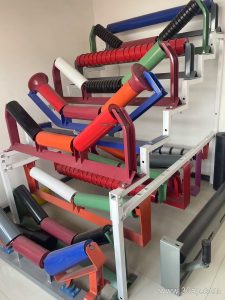
The leg is not chosen in isolation. Its height and its top connection must match the idler frame, which in turn is built around the belt width, the trough angle, and the roller diameter. Common belt widths for support design include B500, B650, B800, B1000, B1200, B1400, B1600, B1800, B2000, B2200. Trough angles of 20, 30, 35, and 45 degrees are widely used, while a forward tilt of about 1.5 to 2 degrees appears on some self-aligning frames. Roller diameters such as Ø89, Ø108, Ø133, Ø159, and Ø194 are typical reference values.
These values are reference data, not fixed pairings. A B800 frame may be built with different roller diameters depending on load and belt speed, and a B1200 run may use either a 35 degree or a 45 degree trough depending on material. The mounting hole spacing and the cross beam length change with belt width and trough angle, so they should always be confirmed against the actual frame drawing rather than assumed.
| Parameter | Common Reference Values | Notes |
|---|---|---|
| Belt width | B500 to B2200 | Selected by capacity and material size |
| Trough angle | 20°, 30°, 35°, 45° | Adjustable frames can change between these |
| Roller diameter | Ø89, Ø108, Ø133, Ø159, Ø194 | Confirm with idler load rating |
| Material | Angle steel, channel steel, folded plate | By load and fabrication method |
Where Conveyor Legs Are Used
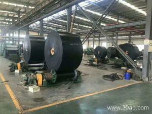
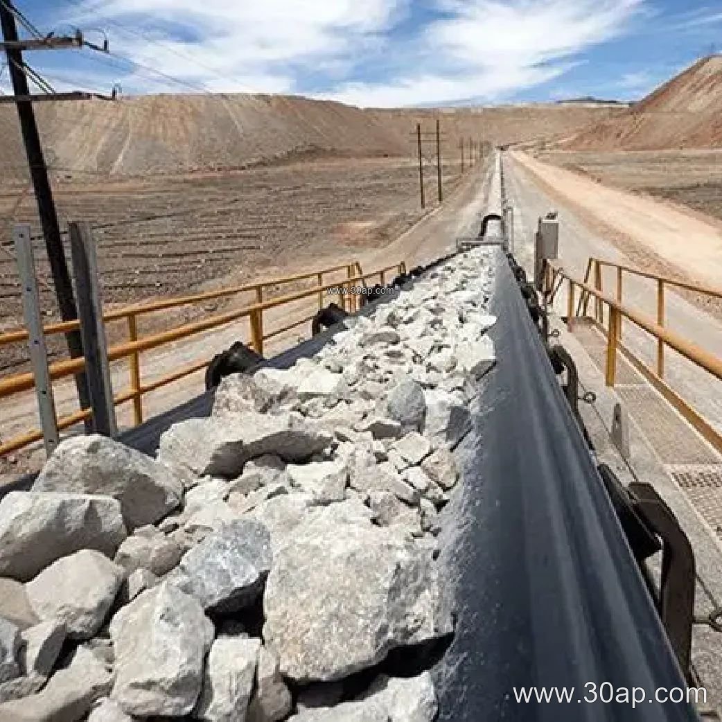
Legs appear wherever a belt conveyor runs above ground on a structural frame. In a limestone mine or an iron ore yard, they support long overland sections exposed to heavy loads and dust. In a coal washing plant or a power plant coal yard, the legs must tolerate a corrosive, dusty atmosphere, and they are often paired with a flame retardant conveyor belt and sealed idler roller bearings to reduce maintenance. In a cement plant, a port terminal, or a batching plant, shorter legs are common on transfer conveyors and on mobile or semi-mobile structures.
The leg also interacts with the belt in ways that are easy to miss. On a steep incline, a skirted conveyor belt or a corrugated sidewall conveyor belt adds material pressure to the frame, and the legs must be sized for that extra load. On a pipe conveyor belt line, the support geometry is different again, and the panel or trestle design replaces the simple leg in many sections. Even a small chevron conveyor belt on a short feeder still needs a stable leg set to keep the belt tracking.
What Buyers Should Confirm Before Ordering
- Belt width, trough angle, and roller diameter of the frame the leg will carry, plus the actual mounting hole spacing.
- Required belt height and whether adjustment is needed on site.
- Load from the belt, material, and any accessories such as a skirted or sidewall belt.
- Foundation type and anchor arrangement, especially on concrete versus steel structures.
- Surface treatment suitable for the environment, from a dry aggregate yard to a wet coal preparation plant.
It also helps to order legs together with the conveyor bracket and the idler roller set, so the hole patterns and heights are consistent. For more on matching support structures with belts and rollers, see chinabeltpro.com conveyor leg pages and related component notes.
Installation and Maintenance Notes
Set out the legs on a string line before anchoring, and check the top elevation against the design belt profile. A leg that is a few millimeters high at a transfer point can lift the belt edge and cause tracking problems that no amount of roller adjustment will fix. After commissioning, inspect the base plates and anchor bolts periodically, particularly in wash plants and ports where vibration and moisture are present. Re-check the adjustable sections after the first weeks of running, since settlement and load can change the belt line height.