What Conveyor Pulley Machining Involves
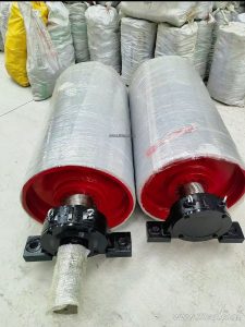
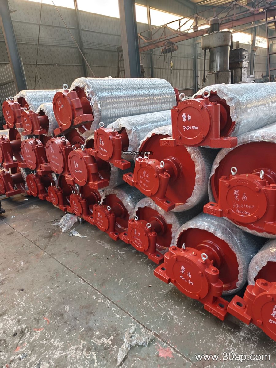
Conveyor pulley machining is the manufacturing stage where a pulley shell, shaft, hub, and end disc are turned, bored, welded, and finished to run true inside a belt conveyor. The work covers the drive pulley at the head, the tail pulley at the return end, and bend or take-up pulleys that route the belt. Each position demands its own machining priorities, so a tail pulley is not simply a cheaper drive pulley. A machined pulley must hold concentricity, balance, and surface quality so the conveyor belt tracks without edge damage and the idler roller set does not fight unnecessary vibration.
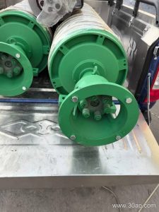
In a typical workshop, the process starts with cutting and rolling the shell, then machining the end discs and hubs. The shaft is turned to fit bearings and coupling details, and the assembly is welded under controlled distortion. Final machining often includes facing the shell ends, boring keyways, and preparing the surface for lagging. For rubber-lagged pulleys, the machined surface provides a stable base for cold-bonded or hot-vulcanized rubber. Buyers who specify conveyor pulley machining should ask for runout records, balance grade, and weld inspection rather than treating the pulley as a simple steel drum.
How the Machining Suits Different Pulley Positions
Drive pulleys transmit torque through the shaft and shell, so machining focuses on hub fit, keyway accuracy, and shaft straightness. Tail pulleys mainly guide and tension the belt, but their machining still matters because a poorly aligned tail pulley can cause mistracking along the whole conveyor. Bend pulleys and take-up pulleys need smooth, true running faces because they often work with a slack side of the belt. In a quarry or aggregate line, a bend pulley with poor concentricity can wear the conveyor belt edge long before the drive pulley shows any problem.
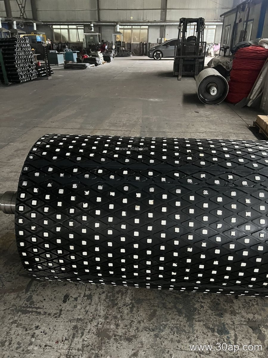
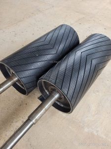
Surface form is another machining decision. A plain machined face suits many non-drive positions, while a grooved or lagged surface improves grip at the drive. Diamond lagging and herringbone lagging are common choices for drive pulleys in wet or dusty service. Ceramic lagging may be considered where slip and abrasion are severe, but the machined base must still be flat and clean. The pulley face width is usually slightly wider than the belt, for example a B800 belt often pairs with a shell around 950 mm wide, but that relationship is a design starting point, not a fixed rule. Shaft diameter depends on torque and load, not on belt width alone.
Where Machined Pulleys Are Used
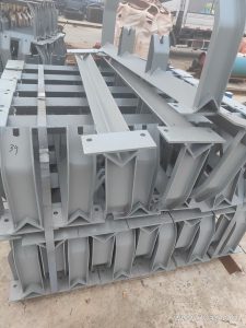
These components appear across bulk handling: a limestone quarry feeding a crusher, a coal washing plant moving product to screens, a cement plant transferring clinker, a power plant coal yard, and a port shiploading line. In each case, the pulley works with a conveyor belt, conveyor idler rollers, and a conveyor bracket that keeps the shaft aligned. The belt type also affects machining choices. An abrasion resistant conveyor belt in a sand and gravel operation may justify extra care on pulley face finish, while a heat resistant conveyor belt near a clinker cooler calls for attention to bearing protection and lagging selection. A flame retardant conveyor belt used underground brings safety requirements that may influence material choice for lagging and covers, but the machining itself still centers on geometry and fit.
For heavy-duty mining conveyor belts and steel cord conveyor belt systems, pulley shells are often larger and shafts heavier. A B1200 × Ø1000 drive pulley and a B1400 × Ø800 bend pulley are plausible combinations in such plants, but the final dimensions come from conveyor design. In a stone crushing line, a B650 tail pulley may be small, yet its machining tolerance still controls belt training. The same logic applies to a pipe conveyor belt or a corrugated sidewall conveyor belt, where pulley faces must match the belt profile and the transition geometry.
What Buyers Should Check Before Ordering
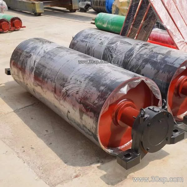
Ask for a drawing that shows shell diameter, face width, shaft diameter, keyway size, bearing seat tolerance, and lagging type. Confirm whether the pulley is a drive, tail, bend, or take-up unit, because these are not interchangeable names. Check the required balancing grade and the inspection method for runout. If lagging is specified, confirm thickness and bonding method; common lagging thicknesses include 8, 10, 12, 15, and 20 mm, but the right value depends on duty. Also verify that the pulley will fit the existing conveyor bracket and that the shaft will accept the chosen coupling or bearing.
Finally, request a machining report that covers material traceability, weld quality, and final dimensions. A well-machined pulley reduces belt splice stress, extends idler roller life, and keeps the conveyor belt centered. Whether the plant handles iron ore, copper ore, fertilizer, or grain, the pulley is a small part of the conveyor but a large factor in uptime. For buyers sourcing through a supplier, clear machining specifications are the best way to avoid a pulley that fits the shaft but not the job.