What a Conveyor System Pulley Does on the Line
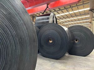
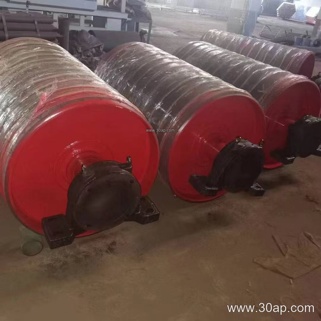
A conveyor system pulley is the rotating drum that turns a conveyor belt, sets its path, and keeps tension stable along the run. It is not a passive part: the head or drive pulley transmits torque from the gearbox to the belt, while the tail pulley closes the loop and the bend pulley redirects the belt where the layout demands. In a quarry or a cement plant, the same word covers several positions, and each position imposes different loads on the shell, shaft, and lagging. The pulley works together with the conveyor belt, the idler roller set, and the conveyor bracket that anchors the assembly to the frame.
Because the pulley is a torque-carrying component, it is usually matched to the belt construction rather than chosen in isolation. A heavy-duty mining conveyor belt on a long incline will call for a larger drum than a short transfer feeding a screen. The right approach is to define the belt tension, belt width, and duty first, then size the drum around them.
How a Conveyor Pulley Is Built
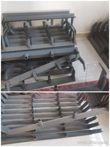
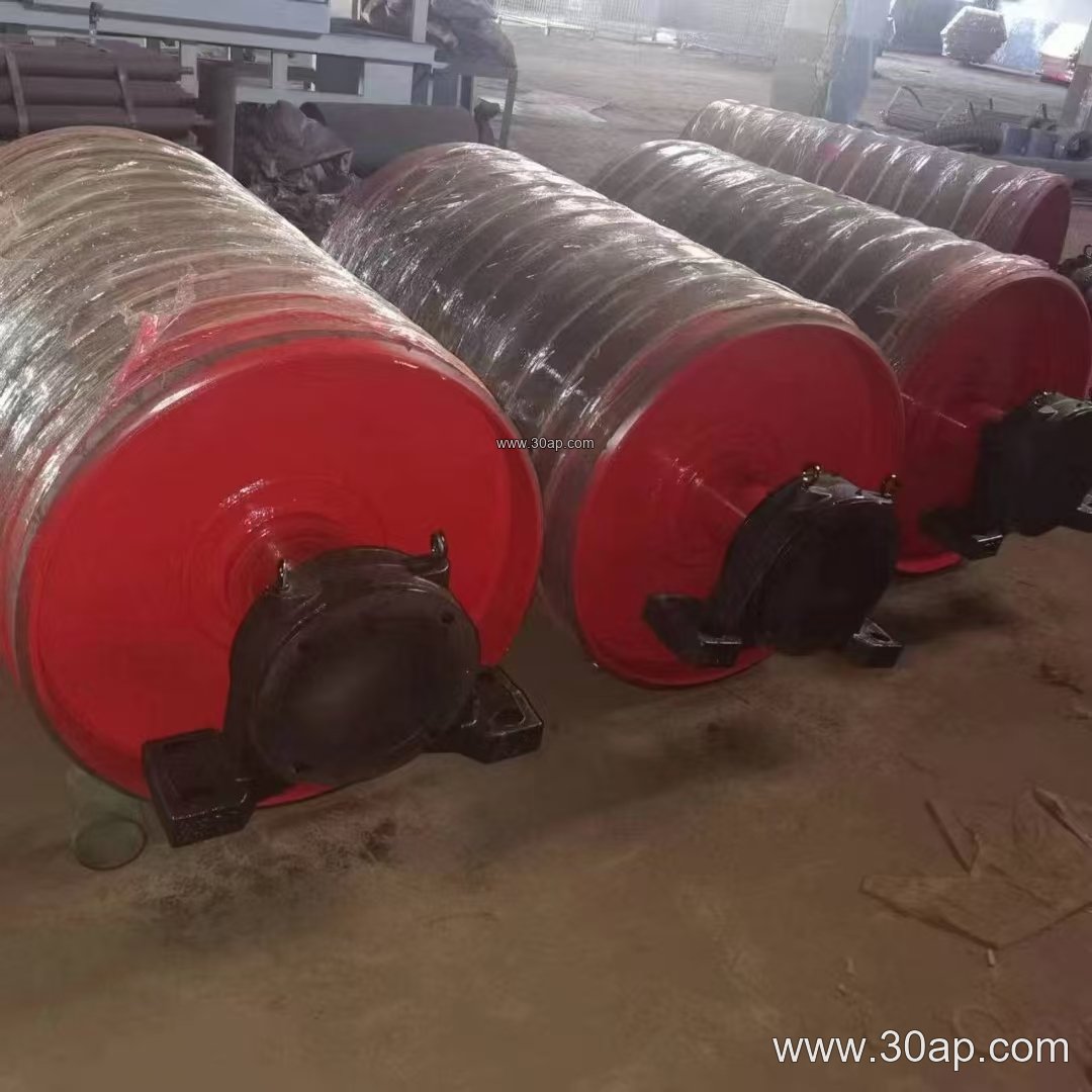
Most industrial drums share a common structure. A rolled steel shell carries a machined shaft, and the shell-to-shaft connection uses welded end discs, hubs, or a keyed assembly depending on the torque. The shell is often crowned slightly to help the belt track, and the surface is finished with plain steel or lagging. Bearings sit in pillow blocks or a split housing, and the whole unit sits on a conveyor bracket welded or bolted to the main frame.
Lagging is where many specifications are decided:
- Plain or smooth finish for light duty and easy cleaning
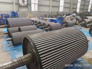
- Diamond pattern lagging for wet or dusty conditions where grip matters
- Chevron lagging for higher traction on incline sections
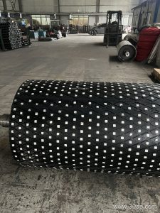
- Ceramic lagging for abrasive service in iron ore or copper ore handling
- Rubber lagging in 8, 10, 12, 15, or 20 mm thickness, applied cold-bonded or hot-vulcanized
Shell width normally runs a little wider than the belt. Typical references include B400 with a shell near 500 mm, B800 near 950 mm, B1200 near 1400 mm, and B1400 near 1600 mm. These are common proportions, not fixed rules, and a designer may adjust them for belt wander or edge clearance.
Where the Drum Fits in the Plant
In a coal washing plant, the drive pulley at the head end pulls a flame retardant conveyor belt through the wash box and discharge chute. In a limestone or aggregate line, the tail pulley may sit inside a tension take-up that moves along the frame as the belt stretches. In a power plant coal yard, a bend pulley redirects the belt around a transfer tower, and the lagging choice often follows the dust and moisture level at that point.
Other positions include the take-up pulley at the gravity or screw tensioner, the snub pulley that increases wrap angle on the drive, and the electric drum used where a compact head is preferred. Each position has its own load profile, so a tail pulley and a drive pulley are never interchangeable even when they share a diameter.
Matching Diameter, Width, and Shaft
Drum diameter is selected from belt tension, belt type, and the minimum bending radius the belt can accept. A steel cord conveyor belt usually needs a larger diameter than a fabric core belt of the same width, because the cords fatigue if bent too tightly. Common diameters in bulk handling range from Ø200 and Ø315 on small units up to Ø1000, Ø1250, and Ø1400 on main drives. Combinations such as B800 × Ø500 or B1200 × Ø1000 appear in real layouts, but no single belt width locks the pulley to one diameter.
Shaft diameter follows torque and bearing load, not belt width alone. Typical shaft sizes include Ø80, Ø100, Ø120, Ø140, and Ø160, with larger sizes on high-torque drives. A buyer should expect the supplier to calculate the shaft from the actual drive power and belt pull rather than pick a number from a width chart.
Buyer Checklist Before Ordering
- Confirm the pulley position: drive, tail, bend, take-up, or snub
- State belt width, belt type, and whether the belt is an abrasion resistant conveyor belt or a heat resistant conveyor belt
- Provide belt speed, motor power, and starting torque so the shaft can be checked
- Specify lagging type and thickness, and whether the surface needs machining after bonding
- Confirm bearing type, housing style, and the interface with the conveyor bracket
- Ask for a balancing report and a runout check on larger drums
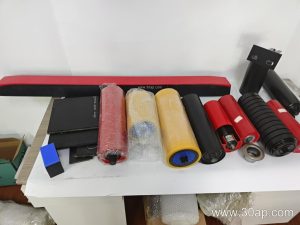
- Check that the shell width and the idler roller alignment in the adjacent section suit the same belt path
Maintenance is straightforward when the drum is accessible. Inspect lagging wear at the drive first, check bearing temperature and grease condition on a schedule, and verify that the belt is not tracking to one side after a lagging replacement. A worn drive pulley with polished lagging will slip long before the belt itself fails, so lagging inspection belongs in the routine walk-down alongside the idler roller check.
For more on matching drums to belts and frames, see the pulley and conveyor component notes at ppipulley.com, where drum sizes, lagging options, and bracket interfaces are described together with the belt specifications they serve.