What a Conveyor Bracket Assembly Actually Holds
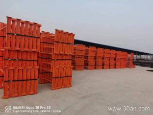
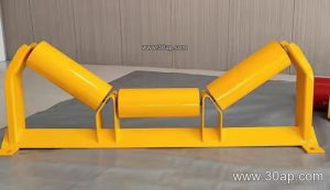
A conveyor bracket assembly is the steel framework that carries the idler roller and keeps the conveyor belt in its intended profile. It is not a single loose part but a matched set of crossmembers, mounting plates, legs or hanger plates, bolt holes and stiffeners that bolt together and fix the roller position relative to the belt line. On a quarry conveyor, a cement plant transfer point or a power plant coal yard, these assemblies are the quiet interface between the belt and the structure.
Buyers often ask for a conveyor bracket by width alone. In practice it is a system: the roller type, trough angle, roller diameter and frame spacing all shape the assembly. A complete assembly should be ordered with the belt width, trough angle, roller diameter and mounting hole spacing stated together, for example B800, 35 degrees, Ø108, because the crossmember length and hole pitch follow the design rather than a fixed number.
How the Assembly Is Built
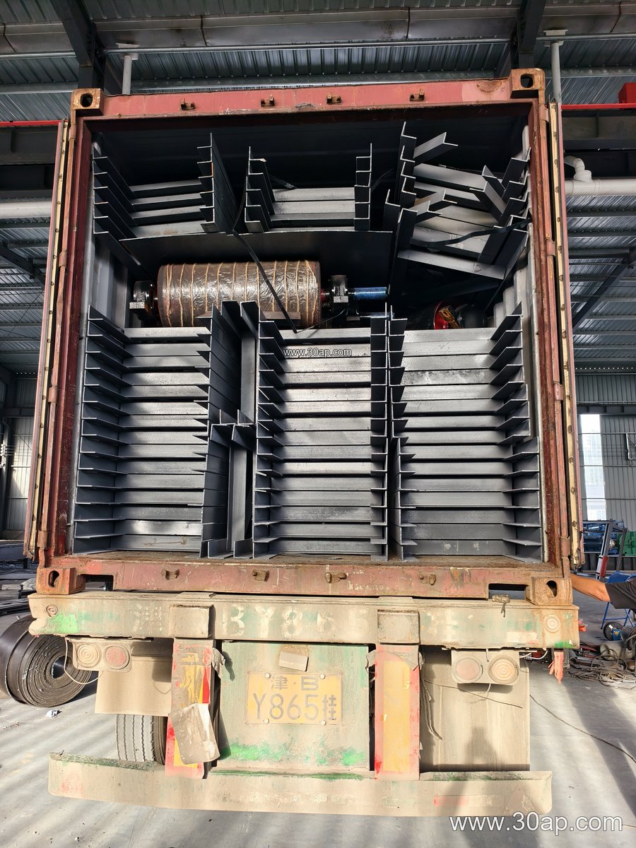
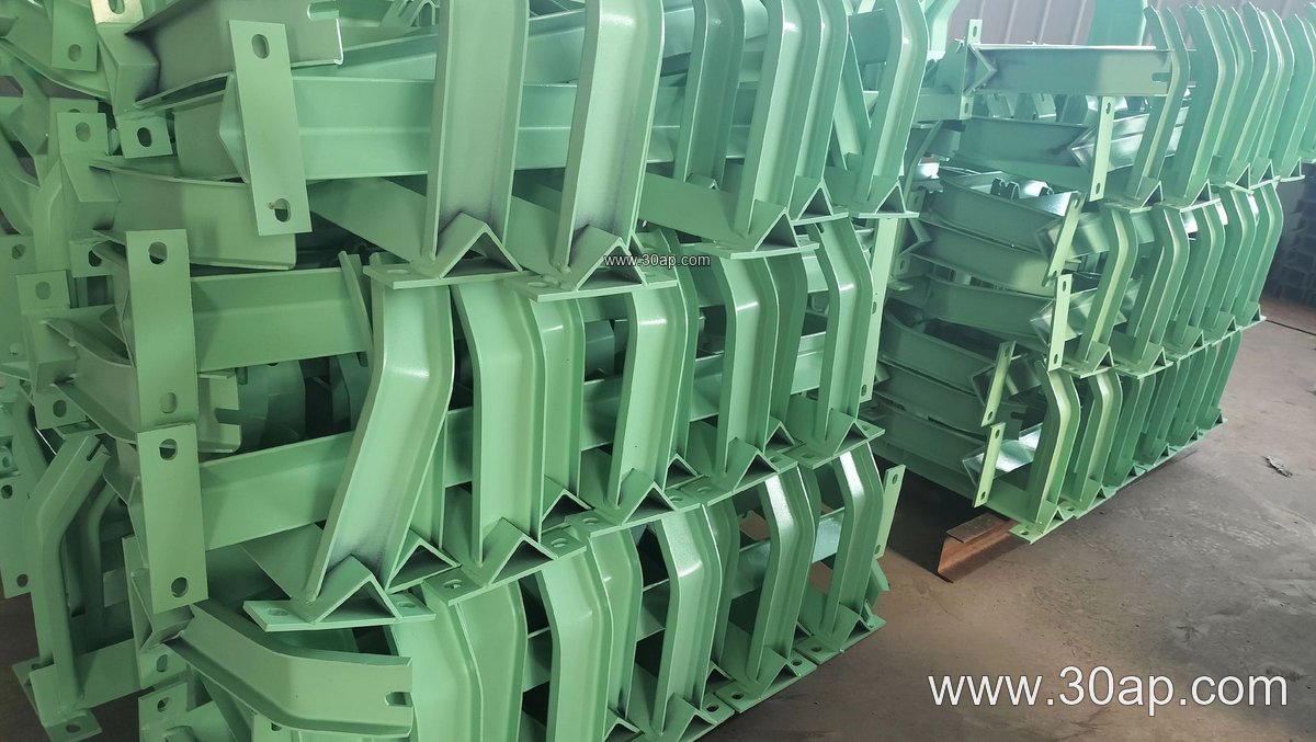
Most units are fabricated from angle steel, channel steel or folded steel plate. Light-duty assemblies may use folded plate with welded end plates; heavier lines in iron ore or crusher discharge areas tend to use channel or angle sections with gusseted joints. The usual pieces are:
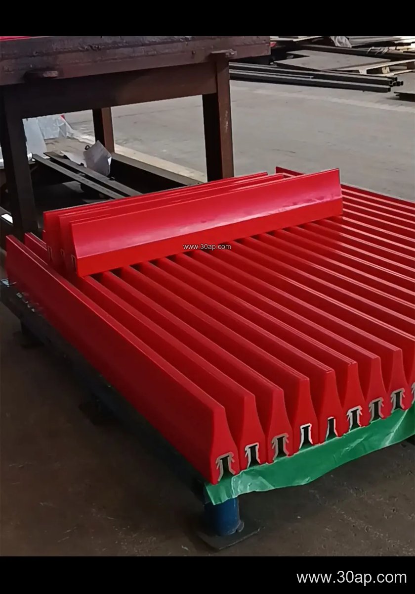
- Two or three roll mounting brackets, angled to set the trough profile
- A crossbeam or stringer that spans the conveyor frame
- Base plates or hanger plates with slotted or drilled holes for adjustment
- Stiffeners, gussets and, where needed, a mounting pad for an impact or self-aligning idler roller
The finish matters as much as the shape. Painted or galvanized assemblies suit general bulk material conveyor belt service; wet washing plants and port terminals often specify a heavier coating. Bolted designs simplify replacement, while welded frames are stiffer but harder to swap in the field.
Common Types and Where They Sit
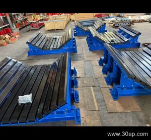
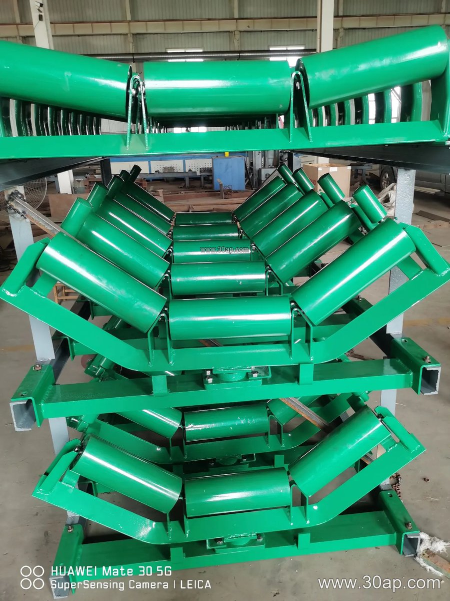
The troughing bracket assembly carries the top run and sets the trough angle. The return bracket carries the lower run, often as a flat or V-return arrangement. Transition brackets sit near the pulley and guide the belt from troughed to flat. Impact brackets are placed under loading points, and self-aligning brackets correct belt wander. Hanger and adjustable versions allow the frame to be leveled or the trough angle to be changed on site.
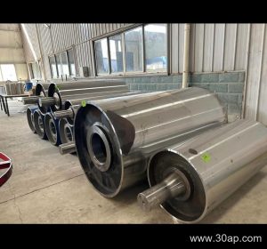
These are not interchangeable with drive, tail or bend pulleys. A bend pulley changes belt direction; a bracket assembly supports the belt and roller. On a long overland line, the same plant may use a drive pulley, a tail pulley and dozens of bracket assemblies, each with a different job.
Typical Reference Data
The values below are common reference ranges, not universal specifications. Final hole spacing and beam length are set by the conveyor design.
Belt width and bracket family
- B500, B650, B800 light and medium troughing frames
- B1000, B1200, B1400 standard quarry and cement plant frames
- B1600, B1800 heavy-duty mining and port frames
- B2000, B2200 extra-wide bulk material conveyor belt lines
Trough angle options
- 20 degrees for flat, wide belts and fine material
- 30 degrees for general aggregate and sand
- 35 degrees for typical crushed rock and ore
- 45 degrees for high-capacity loading and deep troughs
Adjustable brackets can move between these angles. Forward-leaning or leading-angle brackets usually sit around 1.5 to 2 degrees to help belt tracking.
Roller diameter pairing
- Ø89 for narrow, light frames
- Ø108 for B650 to B1000 service
- Ø133 for B1000 to B1400
- Ø159 for heavy B1400 to B1800
- Ø194 for the widest, heaviest lines
These are pairings, not rules. A B1200 frame can be built around Ø133 or Ø159 depending on load and belt speed, and a B800 line may use Ø108 or Ø133. Never assume a shaft diameter from belt width alone.
Where These Assemblies Earn Their Keep
In a limestone quarry, troughing brackets on the primary discharge line must survive sharp rock and dust. In a coal-fired power plant, flame retardant conveyor belt and anti-static conveyor belt grades are common, and the bracket assemblies near the transfer tower need regular inspection for corrosion and loose bolts. In a cement plant, heat resistant conveyor belt may run near the kiln area, and the bracket spacing is tightened to control sag. In a sand and gravel plant, a crusher conveyor belt and the impact brackets beneath the crusher are a frequent wear point.
Whatever the site, the assembly is judged by three things: does the belt sit at the right trough angle, does the idler roller stay square to the frame, and can a fitter reach the bolts safely. Get those right and belt life improves.
Buyer Checklist
- State belt width, trough angle and roller diameter together, for example B1000, 35 degrees, Ø133.
- Confirm mounting hole spacing and crossbeam length against the existing frame, not from a catalogue guess.
- Say whether the frame is bolted or welded, and whether adjustment slots are needed.
- Match the coating to the environment: washdown, coastal air, or dry dust.
- Check that the assembly suits the belt grade in use, whether that is an EP conveyor belt, a steel cord conveyor belt or a fabric core conveyor belt.
- Ask for spare mounting hardware with the first order so field repairs are not delayed.
For more on matching frames with belting and rollers, see the conveyor bracket assembly notes and related technical pages at www.example.com/conveyor-bracket-assembly. A well-specified bracket assembly is a small cost against the belt it protects.