What a Conveyor Idler Frame Does on the Line
A conveyor idler frame is the structural support that holds idler rollers at the correct position under the belt. In many plants the frame is called an idler bracket or idler support frame, and it is the same product: a steel crossmember assembly that keeps each roller aligned so the belt runs smoothly from loading point to discharge. The frame carries the roller, the roller carries the belt, and the belt carries the material. When the frame is weak, twisted, or mounted at the wrong height, the belt starts to wander, spillage increases, and roller bearings fail early.
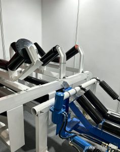
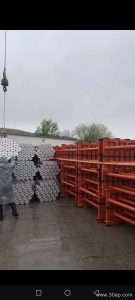
Frames appear on both sides of the belt path. Trough frames sit on the carrying side and hold two or three rollers in a V or trough shape. Return frames sit under the belt and support the empty strand, often with a single flat roller or a pair of rollers set in a V. On a quarry conveyor belt or a power plant coal line, these frames are repeated every few metres, so small dimensional errors add up over a long run.
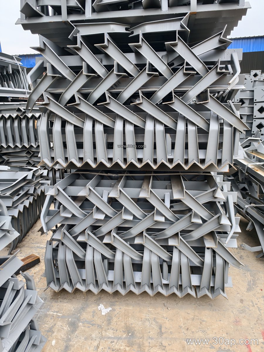
How the Frame Is Built
Most frames are fabricated from angle steel, channel steel, or folded steel plate. The crossbeam is drilled or slotted to match the roller shaft ends, and the ends of the beam are fitted with feet or hooks that attach to the conveyor stringer. Common constructions include fixed welded frames, bolted frames, and adjustable frames that allow the trough angle to be changed on site.
The working geometry is usually described by belt width, trough angle, and roller diameter together. For example, a frame for B800 belt at 35 degrees with Ø108 rollers is a normal combination, and a B1200 line at 45 degrees with Ø133 rollers is equally common. These are design choices, not fixed rules. Installation hole spacing and beam length follow the belt width and trough angle, so they should be confirmed against the conveyor drawing rather than assumed.
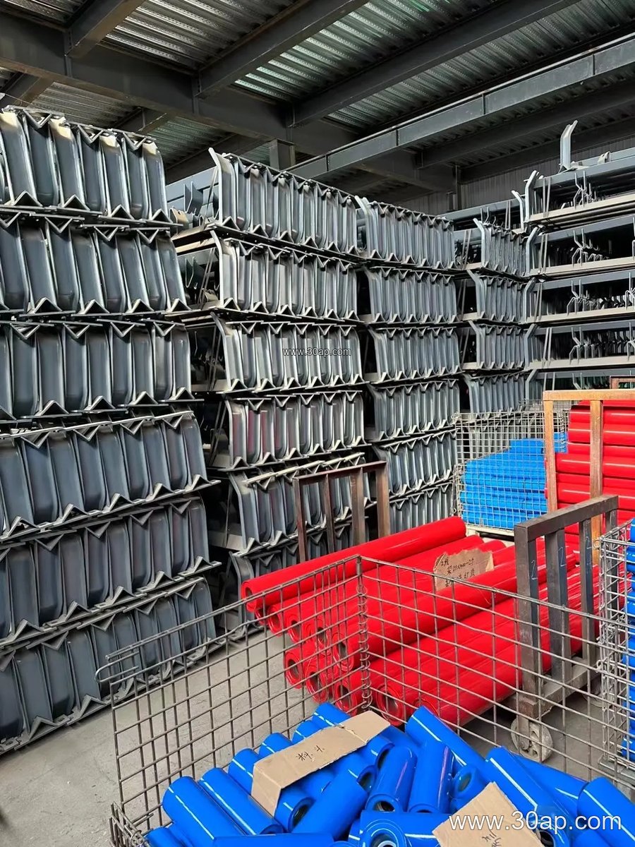
| Frame Type | Typical Position | Common Notes |
|---|---|---|
| Trough frame | Carrying side | 20, 30, 35, or 45 degree trough |
| Transition frame | Near pulleys | Gradual change of belt shape |
| Impact frame | Loading point | Extra support under the chute |
| Return frame | Empty strand | Flat or V return rollers |
| Self-aligning frame | Long straight runs | Helps correct belt drift |
| Adjustable frame | Varies | Trough angle can be reset |
Matching the Frame to Belt and Roller
On a heavy-duty mining conveyor belt, the frame must resist shock from large lumps and keep the rollers square to the belt. At a crusher discharge or a transfer chute, impact frames with closely spaced rollers reduce the chance of belt damage. On a long overland line carrying an EP conveyor belt or a steel cord conveyor belt, trough frames are spaced for sag control, while return frames are spaced for belt weight and wind load.
Roller diameter and frame height are linked through the shaft and the mounting slot. A Ø89 roller on a small B650 frame will not fit a frame built for Ø159 rollers, and a frame for a 45 degree trough needs a different beam profile from a 20 degree frame. Buyers should supply the belt width, the required trough angle, the roller diameter, and the mounting method. Where the belt is a pipe conveyor belt or a corrugated sidewall conveyor belt, the frame layout is usually part of the special conveyor design and should be checked with the original equipment drawing.
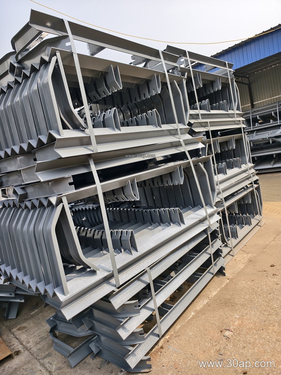
Where Frames Are Used
These frames are found in limestone quarries, iron ore plants, coal washing plants, cement kilns and clinker lines, power station coal handling, port ship loaders, and aggregate crushing and screening plants. In a sand and gravel line, trough frames carry abrasive aggregate and return frames support the clean side of the belt. In a fertilizer or grain silo, frames may be galvanized or painted for corrosion resistance.
The frame does not work alone. It pairs with the conveyor belt, the idler roller, the conveyor pulley at each end, and the conveyor bracket that ties the structure together. A well-aligned frame set keeps the belt centred, protects the pulley lagging, and reduces spillage at transfer points.
Buyer Checklist
- Confirm belt width, trough angle, and roller diameter as a set.
- State whether the frame is fixed, adjustable, impact, or self-aligning.
- Check mounting hole spacing and beam length against the stringer drawing.
- Choose the steel finish for the site: painted, galvanized, or bare.
- Ask for the frame drawing before production, especially for transition and return positions.
Ordering by belt width alone is not enough. A clear drawing that shows the roller centres, the trough angle, and the mounting points prevents site rework and keeps the conveyor running straight.