What an Integral Pulley Is
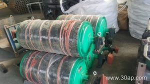
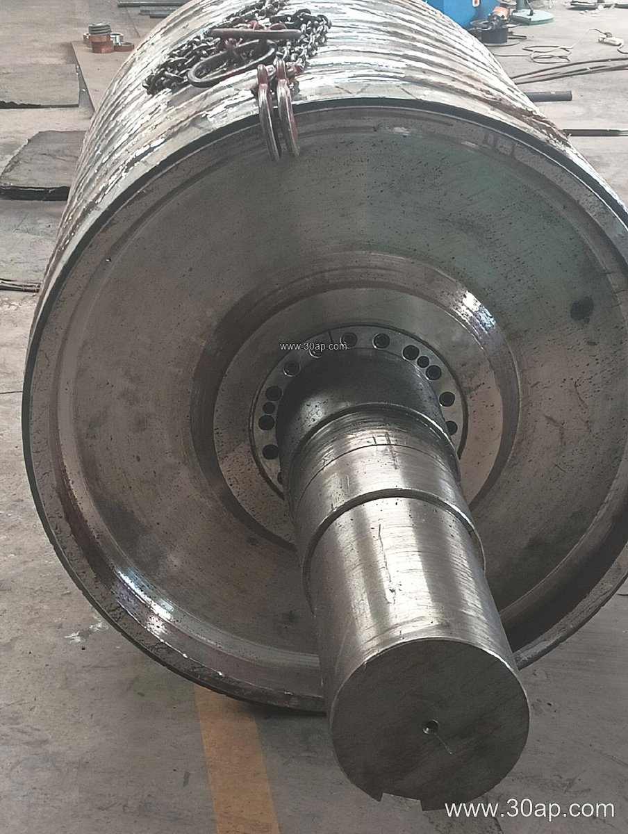
An integral pulley is a conveyor pulley whose shell, end discs, and hub assembly are built as one continuous welded structure rather than a shell slipped over a separate shaft-and-hub arrangement. In practice, the term is used alongside the more general name conveyor pulley, and the two describe the same component when the drum body is fabricated as a single welded unit. The design is common on medium and heavy bulk handling lines where the pulley must carry high belt tension without loosening at the joints.
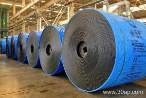
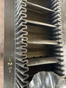
Because the shell and discs act together, an integral drum tends to hold its roundness under load, which helps the belt track steadily. This matters on long overland runs, in primary crushing circuits, and wherever a Rubber Conveyor Belt is asked to move abrasive rock at high tonnage.
How the Drum Is Built
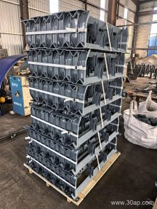
Fabrication usually starts with a rolled steel shell, to which end discs are welded and then machined so the shaft seats true. The shaft is fitted through the hubs and keyed or shrink-fitted, and the whole assembly is balanced before the surface treatment goes on. A machined face, a rubber covering, or a ceramic tile layer can then be applied depending on the duty.
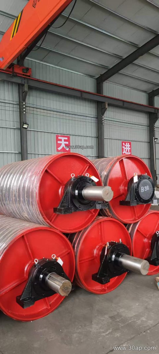
- Rolled shell with welded end discs and hubs
- Machined shaft seating and balanced rotation
- Plain, rubber lagged, diamond, chevron, or ceramic surface
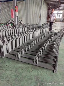
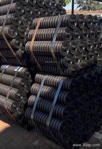
- Bearing housings and conveyor bracket mounts matched to the frame
Lagging thickness is commonly 8, 10, 12, 15, or 20 mm, and the choice depends on grip requirements and the abrasiveness of the material. A diamond or chevron pattern improves traction on wet or dusty belts, while plain rubber suits cleaner duty.
Where Integral Drums Are Used
These pulleys appear across quarry and aggregate lines, cement plants handling clinker, power station coal yards, and iron or copper ore concentrators. In a stone crushing circuit they often sit at the head of a Bulk Material Conveyor Belt as the discharge drum, and at the tail as the tension drum. Port bulk terminals use large versions on ship loading conveyors, and sand and gravel plants rely on them on short transfer belts feeding screens.
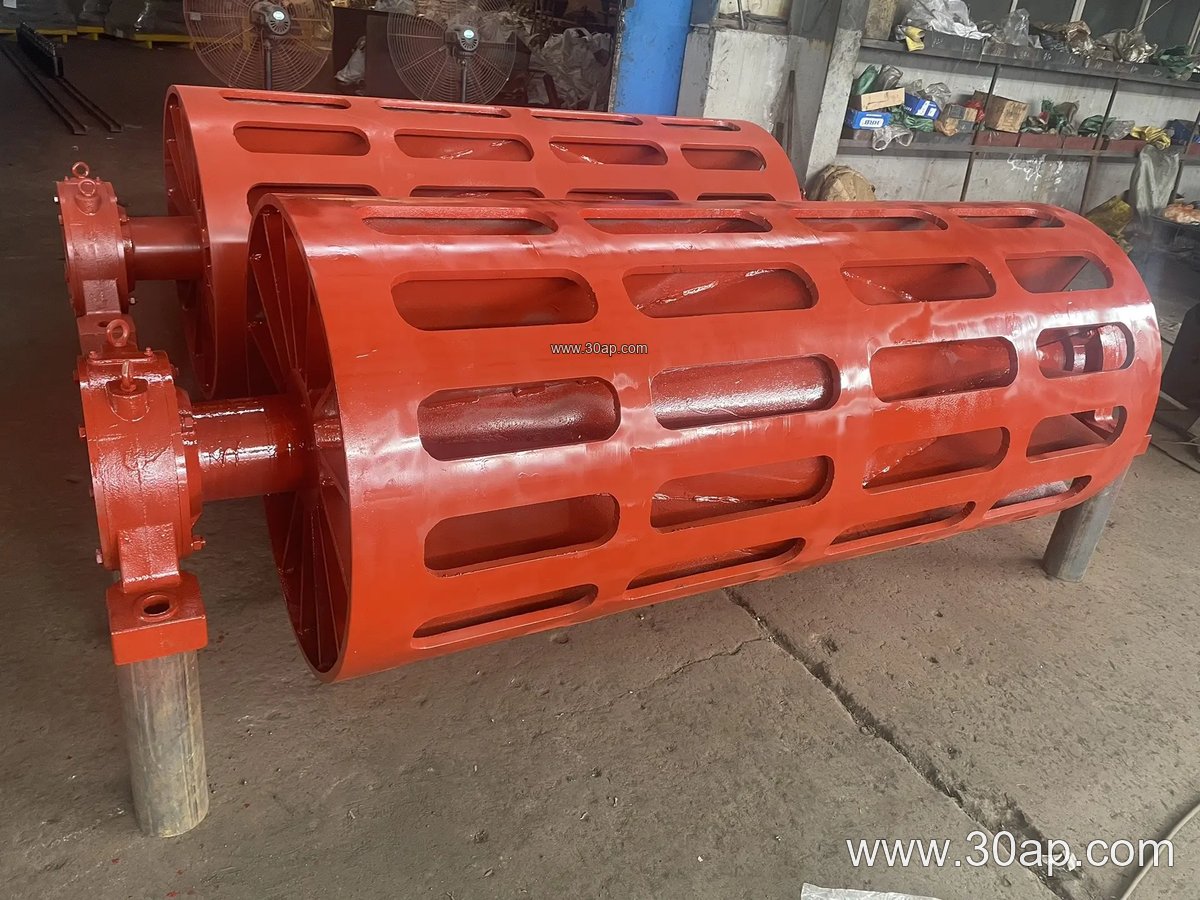
It is worth noting that a drive pulley and a tail pulley are not interchangeable: the drive transmits torque through lagging and shaft, while the tail mainly redirects and tensions the belt. A bend pulley serves yet another role. When specifying, keep these positions distinct rather than treating them as one part.
Matching Pulley to Belt Width
Shell face width is normally a little wider than the belt it carries, so a B800 belt typically runs on a face around 950 mm, and a B1200 belt on roughly 1400 mm. Diameter is set by belt tension, wrap angle, and the allowable bearing load, not by belt width alone. Common combinations include B800 x Ø500 and B1200 x Ø1000, but these are examples rather than fixed rules.
| Belt width | Typical face width | Example diameter range |
|---|---|---|
| B500 | about 600 mm | Ø250 to Ø400 |
| B650 | about 750 mm | Ø315 to Ø500 |
| B1000 | about 1150 mm | Ø400 to Ø800 |
| B1400 | about 1600 mm | Ø630 to Ø1000 |
| B1800 | about 2000 mm | Ø800 to Ø1250 |
Shaft diameter follows torque and load calculations; Ø80, Ø100, Ø120, and Ø160 are common, but a given belt width does not dictate a single shaft size.
Buyer Checklist
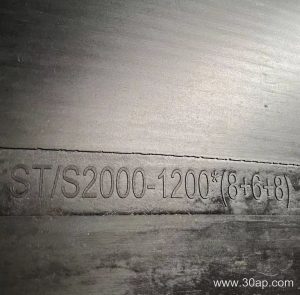
Before ordering, confirm the belt width and the belt type in service, since an EP Conveyor Belt and a steel cord belt load the drum differently. Ask for the wrap angle, the required lagging pattern and thickness, and the bearing arrangement. Check that the frame and idler roller heights line up with the proposed drum diameter so the belt line stays level.
For hot or oily duty, state the condition clearly so the lagging compound suits the environment. On coal handling lines, flame retardant and anti-static properties of the belt are usually specified separately, and the pulley surface should match that duty. Finally, request balancing data and a drawing showing shaft, keyway, and bearing centers so installation on site goes smoothly.