What a Mining Idler Does on a Conveyor
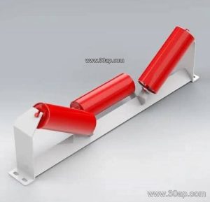
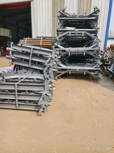
A mining idler is the rotating roller assembly that supports the conveyor belt along its carrying and return runs. In a quarry, iron ore plant or coal handling line, the belt may carry hundreds of tonnes per hour, and the idlers take the load, guide the belt and keep friction low. The idler roller itself is a tube with bearings and a shaft, mounted in a frame or conveyor bracket so it turns freely under the belt.
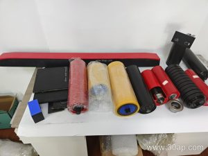
The term covers several positions on the same conveyor. Troughing idlers form the belt into a trough on the carrying side, return idlers support the empty belt underneath, and impact idlers absorb the drop at loading points. These are different duties on the same machine, and each is selected for its own job.
Construction and Main Parts
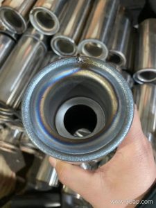
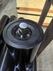
A typical idler roller has a steel shell, welded end discs, a through shaft, bearing housings and a sealing arrangement. The shell may be plain steel, nylon-coated, ceramic-covered or fitted with rubber rings for impact absorption. Bearing size is matched to load and speed rather than to belt width alone; common bearing numbers include 6204, 6205, 6305, 6306, 6308 and 6310.
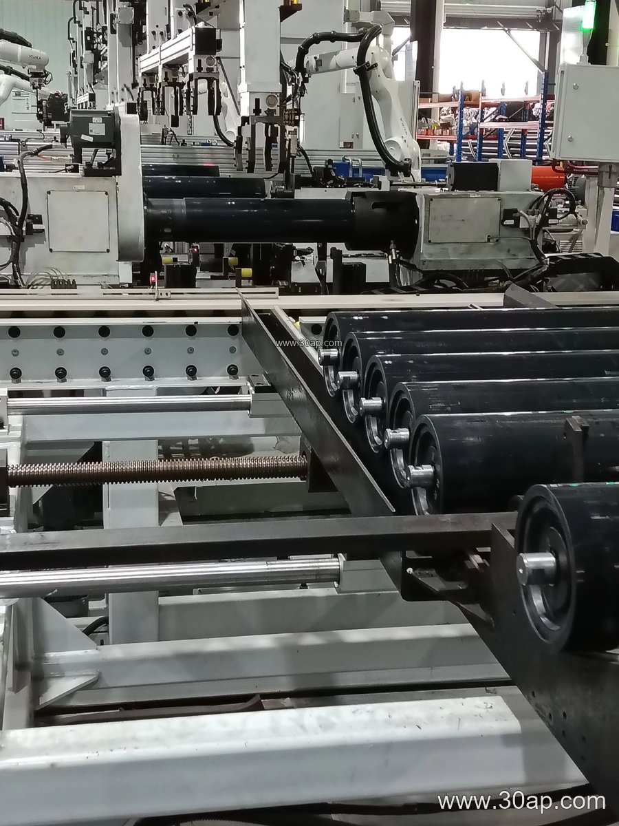
Sealing matters in dusty and wet conditions. Labyrinth seals and multi-stage dust seals are common where fines and water are present. The roller must spin freely but also resist ingress, because a seized idler can wear through a belt quickly.
Where Mining Idlers Are Used
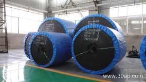
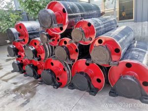
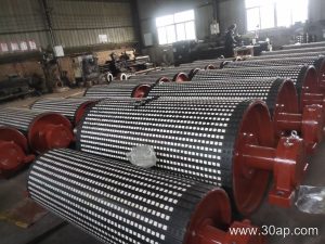
You will find these rollers in crushing and screening plants, limestone and copper mines, coal preparation plants, cement works and power station coal yards. They also appear in port bulk terminals and tunnel spoil handling. In each case the conveyor belt is the working surface, while the idlers and conveyor pulley set the belt path.
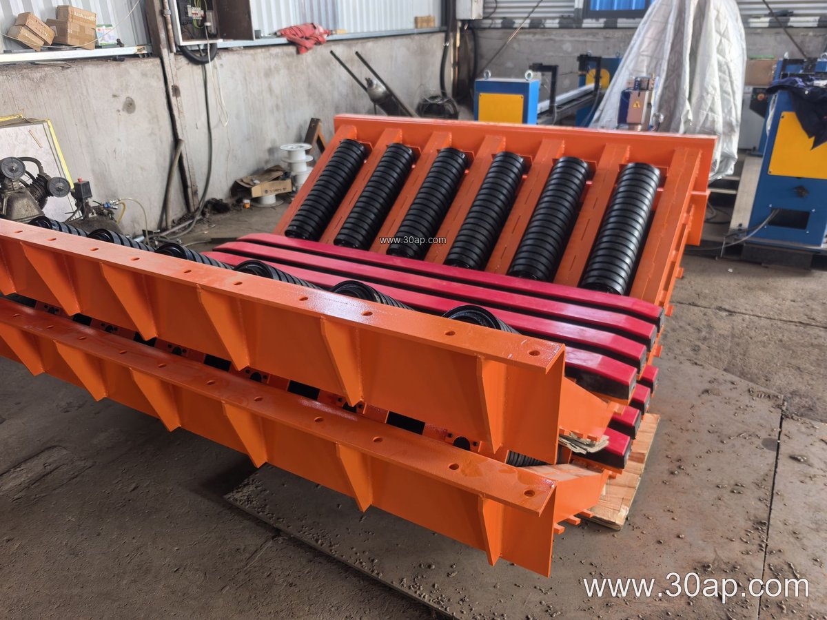
On a primary crusher discharge, impact idlers with rubber rings are often used to cushion falling rock. Along the main haulage run, three-roll troughing sets at 20, 30, 35 or 45 degrees are common, with the trough angle chosen to suit material lump size and belt width. On the return side, flat or V-return idlers keep the belt in line.
Common Sizes and Arrangements
Idler diameter and length follow the belt width, load and trough geometry. The table below gives typical reference values; final dimensions are set by the conveyor design.
| Belt width | Typical three-roll troughing idler length | Common roller diameter range |
|---|---|---|
| B500 | about 200 mm | Ø63 to Ø89 mm |
| B650 | about 250 mm | Ø76 to Ø108 mm |
| B800 | about 315 mm | Ø89 to Ø127 mm |
| B1000 | about 380 mm | Ø102 to Ø133 mm |
| B1200 | about 465 mm | Ø108 to Ø159 mm |
| B1400 | about 530 mm | Ø127 to Ø178 mm |
| B1600 | about 600 mm | Ø133 to Ø194 mm |
| B1800 | about 670 mm | Ø159 to Ø219 mm |
Side rollers and centre rollers can differ in length, and a two-roll or single-roll arrangement may suit a narrow or special belt. Self-aligning idlers, including friction and tapered types, are used where the belt tends to wander. Spiral and comb idlers are chosen for sticky material that would otherwise build up on the shell.
Buyer Checklist
- Match the idler to the belt width and trough angle, not just to the belt specification.
- Confirm shaft diameter and bearing series with the frame or bracket dimensions.
- State the environment: dust, water, coal dust, heat or oil, so seals and covers are suitable.
- Check that the roller surface suits the material; rubber rings help at impact points.
- Ask for the idler length, diameter and mounting dimensions as a drawing, since these vary by design.
- Plan spare rollers for the loading zone and return run, where wear is often fastest.
A conveyor is a system, so the belt, idlers, pulleys and brackets work together. A well-chosen mining idler keeps the belt tracking, reduces power draw and extends the life of the whole line. For related equipment, see our conveyor belt, conveyor pulley and conveyor bracket pages.