What the Conveyor Belt Support Frame Does
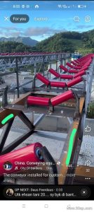
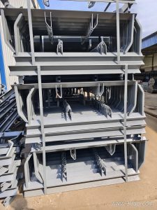
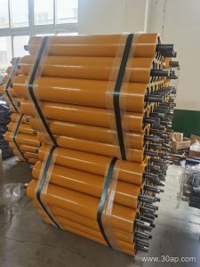
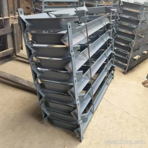
A conveyor belt support frame is the steel structure that carries the idler rollers and holds the belt in its working profile. On a typical troughed conveyor, the frame sits between the stringers or stands on the conveyor brackets, and it is the part that decides the trough angle, the roller spacing and the height of the belt line. In a quarry, a cement plant or a power station coal yard, the frame is what turns a flat rubber belt into a stable carrying surface.
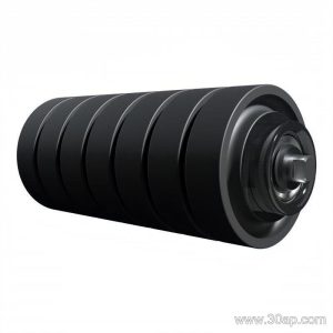
The frame is not the same as a pulley. Drive pulleys, tail pulleys and bend pulleys are rotating drums that transmit power or change belt direction; a support frame is a static fabrication that supports rollers. The two work together on the same conveyor but serve different purposes.
How the Frame Is Built
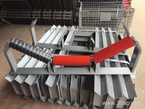
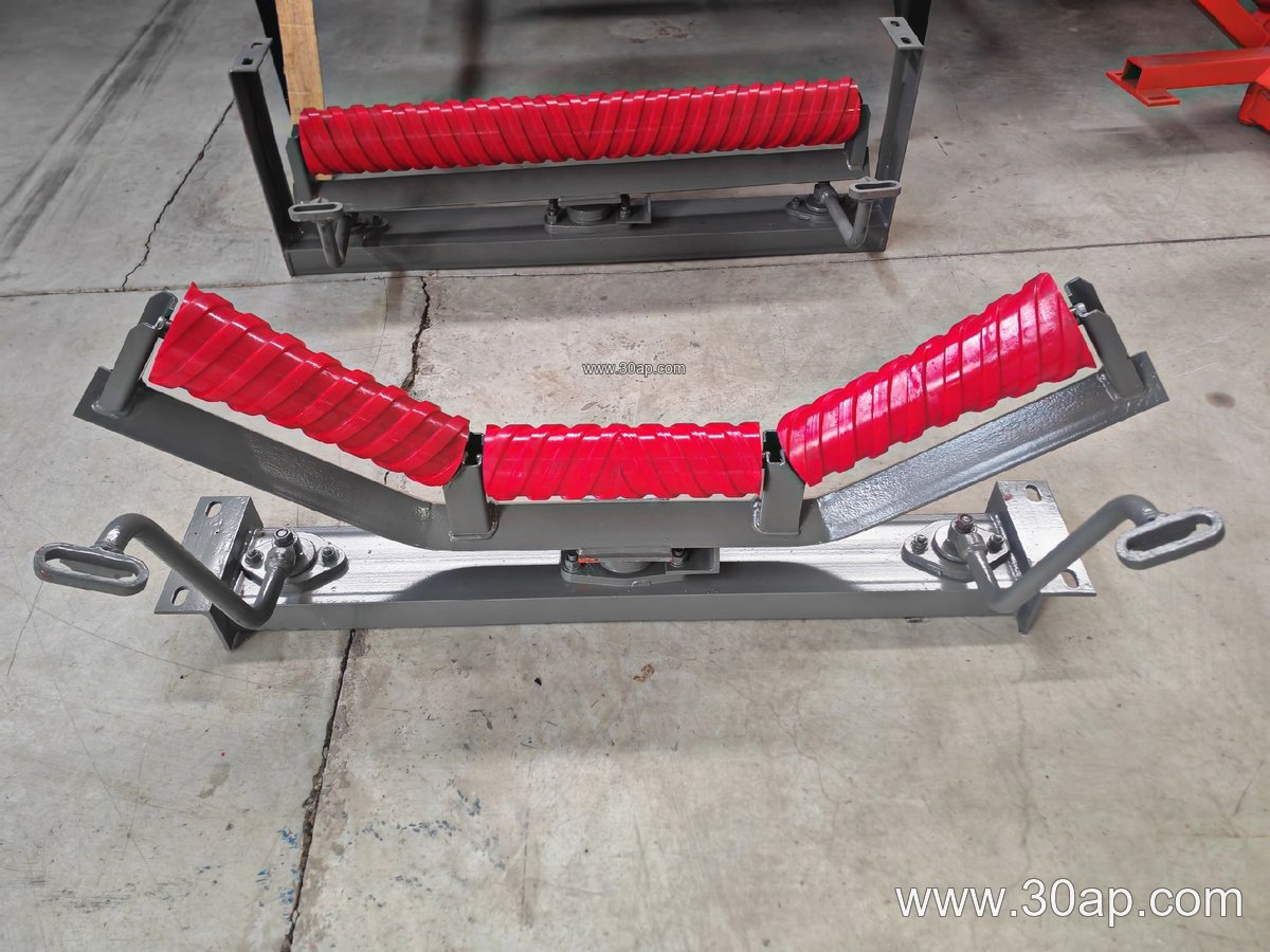
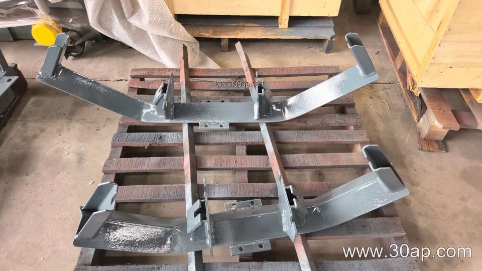
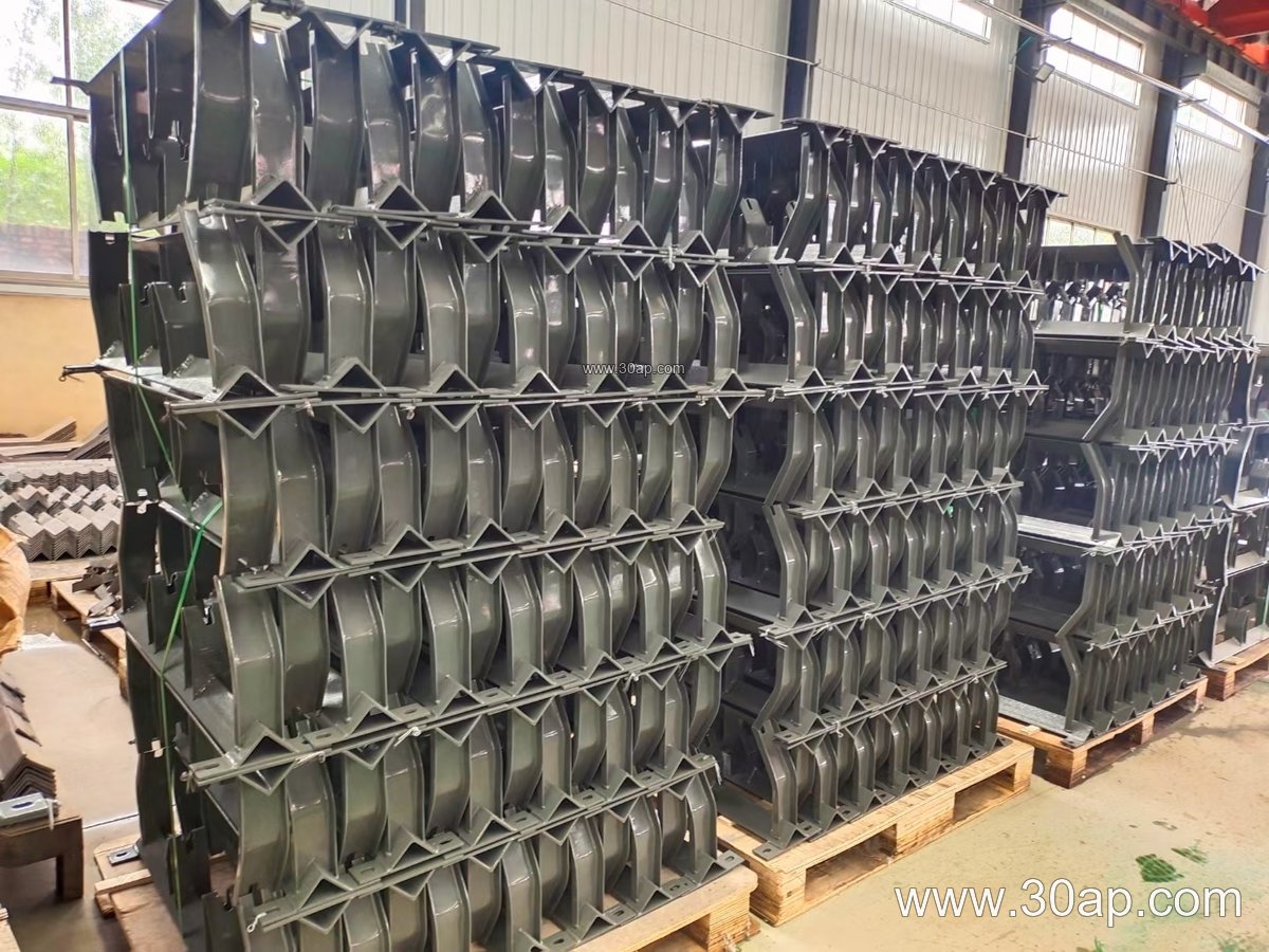
Most frames are fabricated from angle steel, channel steel or folded steel plate. The cross beam carries the roller mounts, and the end fixings connect to the conveyor structure. Common forms include:
- Upper trough frames that set the carrying idlers at 20, 30, 35 or 45 degrees
- Transition frames used where the belt changes from flat to troughed
- Return frames, including flat return and V-shaped return designs
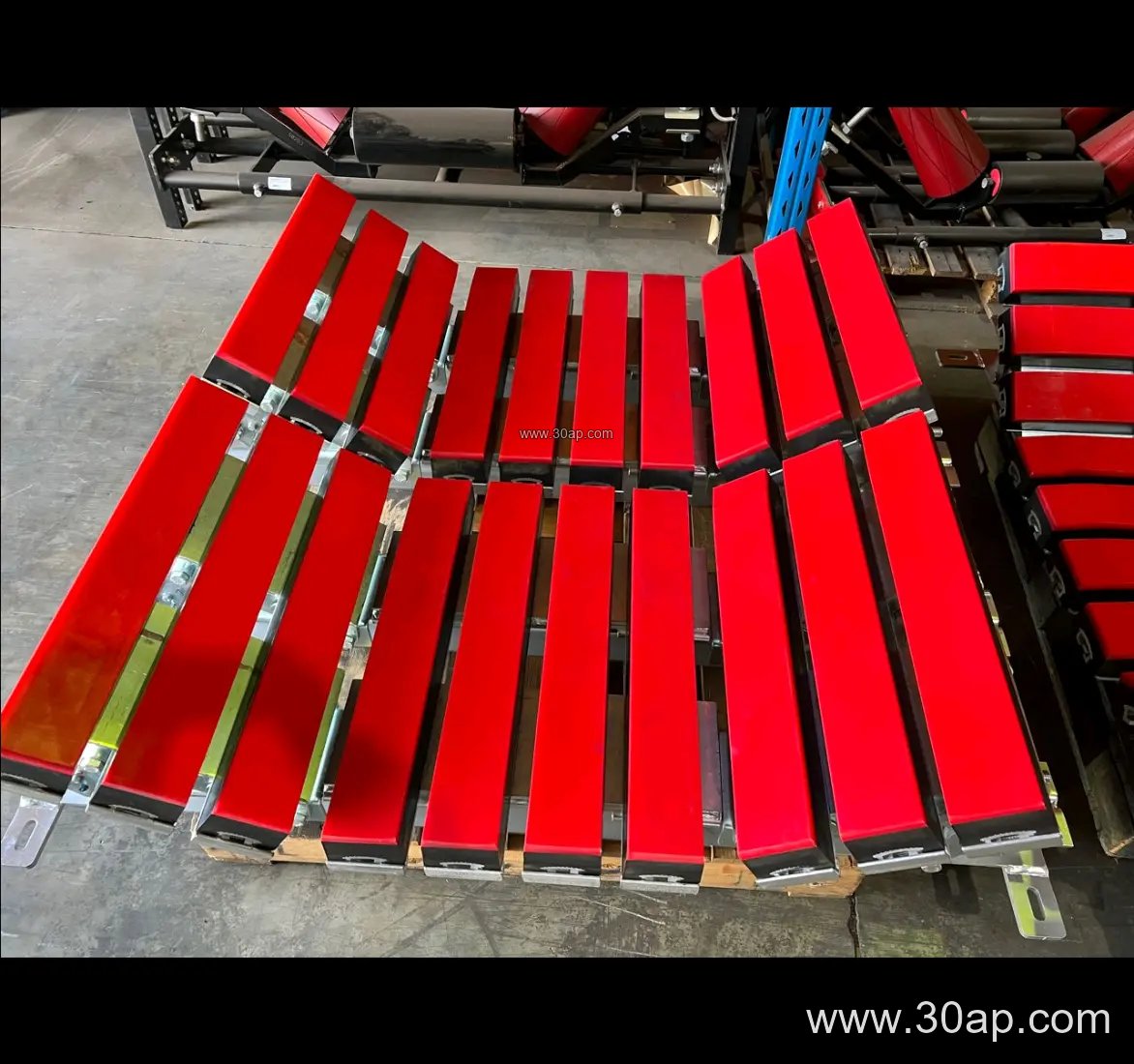
- Impact frames that carry buffer rollers under the loading point
- Self-aligning and forward-leaning frames for belt tracking
- Suspended and adjustable frames for lines where the trough angle or height must be trimmed on site
An adjustable support frame allows the trough angle to be changed within a range instead of being fixed at one value. Forward-leaning frames usually set the side rollers at about 1.5 to 2 degrees ahead of the belt direction, which helps keep the belt centred.
Matching Frame, Belt Width and Roller Diameter
Frame size follows the belt width, and the roller diameter is chosen from load and speed rather than from width alone. A B800 belt may run with Ø89 or Ø108 rollers, while a B1200 line in a crushing and screening plant often uses Ø133. The table below shows typical reference combinations; actual mounting hole spacing and beam length are determined by the design.
| Belt width | Typical trough angle | Typical roller diameter |
|---|---|---|
| B500 / B650 | 20 to 30 degrees | Ø89 |
| B800 / B1000 | 30 to 35 degrees | Ø108 to Ø133 |
| B1200 / B1400 | 35 to 45 degrees | Ø133 to Ø159 |
| B1600 / B1800 | 35 to 45 degrees | Ø159 to Ø194 |
| B2000 / B2200 | 35 to 45 degrees | Ø159 to Ø194 |
These are common ranges, not fixed rules. A wide belt can run at a modest trough angle, and the same width may be supplied with different roller diameters depending on the duty.
Where It Is Used
You will find these frames on almost any continuous bulk handling line. In a limestone mine or aggregate plant, trough frames carry the belt through the crushing and screening circuit. In a coal washing plant and a power station coal yard, return and self-aligning frames keep the belt tracking on long runs. Cement plants use impact frames under the clinker and raw material loading points. In a port terminal or a grain silo, the frame layout is often designed for easy roller replacement from one side.
What a Buyer Should Check
- Belt width and the required trough angle, including whether adjustment is needed
- Roller diameter, idler type and the spacing the frame must accept
- Steel section, finish and the mounting interface with the conveyor bracket
- Loading conditions at transfer points, which may call for buffer frames
- Whether the frame is fixed or adjustable, and the tracking behaviour of the line
- Availability of matching spare parts for future maintenance
Ask for a drawing that shows hole spacing and beam length for your belt width rather than accepting a generic size. A well-matched conveyor belt support frame keeps the belt, rollers and pulleys working as one system, and it is far easier to service than a frame that was chosen by width alone.